
System and method for detecting leakage of nuclear reactor coolant using laser induced emission spectrum

a nuclear reactor and laser emission technology, applied in instruments, greenhouse gas reduction, optical radiation measurement, etc., can solve the problems of difficult to analyze elements having a small atomic weight, difficult to detect the leakage of coolant either in advance, and the atmosphere between the sample and the detector must be controlled

Inactive Publication Date: 2014-10-07
KOREA ATOMIC ENERGY RES INST
View PDF16 Cites 7 Cited by
  • Summary
  • Abstract
  • Description
  • Claims
  • Application Information

AI Technical Summary

Benefits of technology

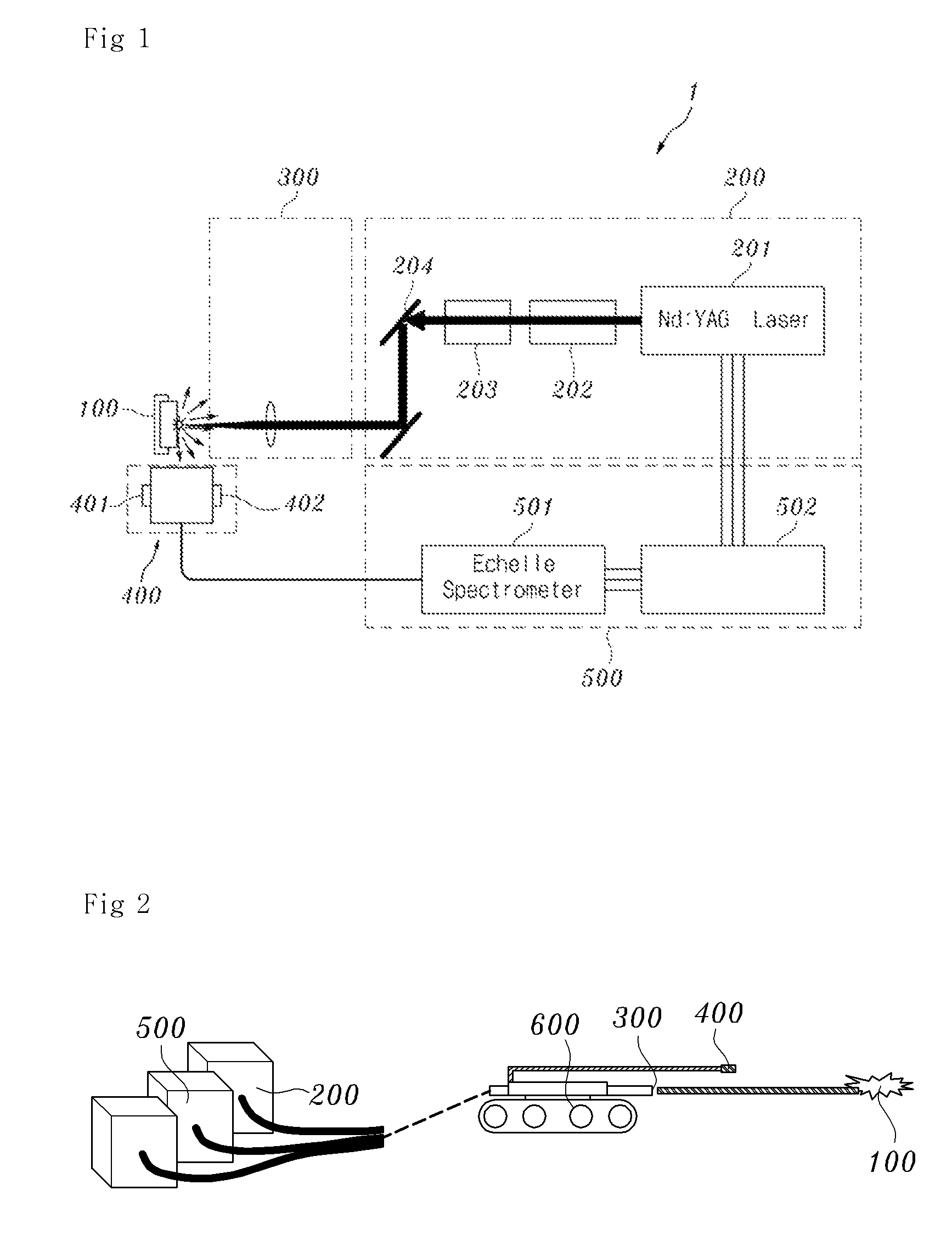
This patent describes an apparatus for detecting leaks in nuclear reactor coolant. It uses a laser beam to induce a plasma emission on a target material, and collects the light emitted during this process using a laser focusing lens and an emission spectrum analyzer. The apparatus also includes an ultrasonic generation laser or a compressed air jetting device to temporarily eliminate water from the target material's surroundings. A suction filter is also included to eliminate impurities from the emitted light collector. The technical effect of this patent is to provide a reliable and accurate method for detecting leaks in nuclear reactor coolant.

Problems solved by technology

In spite of these conventional leakage detection methods, it is currently very difficult to detect the leakage of a coolant either in advance or when the amount of coolant leaked is small.
However, this method makes it difficult to analyze elements having a small atomic weight, such as boron.
There is a disadvantage in that in order to analyze elements having a small atomic weight, the atmosphere between the sample and the detector must be controlled.
Further, there is a limitation in that it is difficult to apply such methods to highly radioactive environments such as the surroundings of a nuclear reactor, or to samples having high radiation levels.

Method used


Image

  • System and method for detecting leakage of nuclear reactor coolant using laser induced emission spectrum
  • System and method for detecting leakage of nuclear reactor coolant using laser induced emission spectrum
  • System and method for detecting leakage of nuclear reactor coolant using laser induced emission spectrum

Examples


Embodiment Construction

[0034]Hereinafter, embodiments of the present invention will be described in detail with reference to the attached drawings. Reference now should be made to the drawings, in which the same reference numerals are used throughout the different drawings to designate the same or similar components. When the present invention is described, detailed descriptions of the related well-known functions or constructions will be omitted to prevent the gist of the present invention from being unclear.

[0035]The present invention, in its various embodiments, provides systems and methods for detection and analysis of impurities generated at the pressure boundary of the primary system of nuclear reactor. According to some embodiments, the system and method of the invention detect the leakage of nuclear reactor coolant that may occur in nuclear power plants and predicted early. In some embodiments, the system and method for detecting and predicting the leakage of nuclear reactor coolant using a laser ...


PUM

PropertyMeasurementUnit
wavelength rangeaaaaaaaaaa
diameteraaaaaaaaaa
diameteraaaaaaaaaa

Abstract

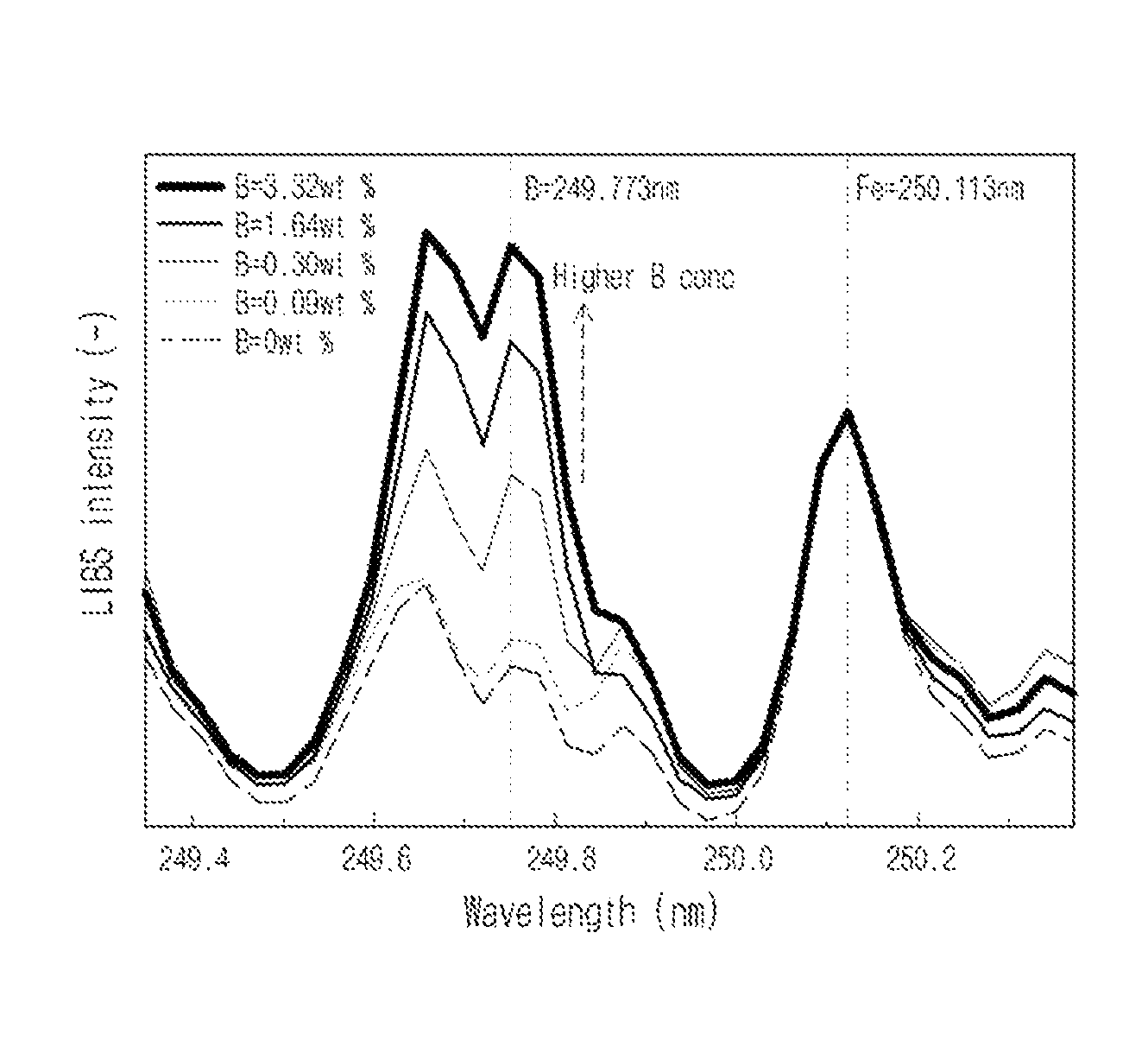
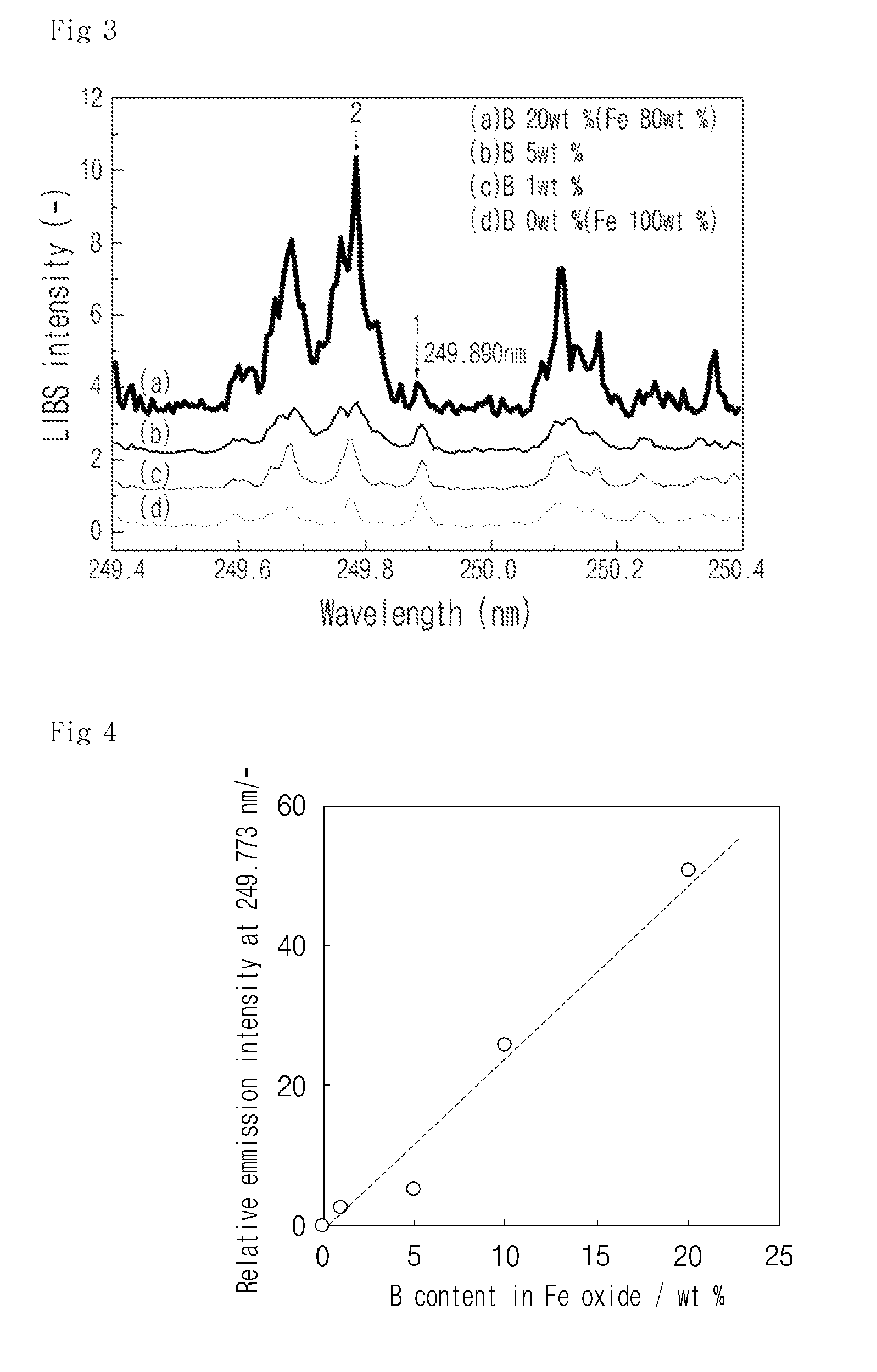
System and method for detecting and / or predicting in a field the leakage of nuclear reactor coolant that may occur at the pressure boundary of the primary system of a nuclear reactor. The system and method for detecting the leakage of nuclear reactor coolant uses a laser induced emission spectrum. The leakage of coolant is detected by detecting boron (B), a main component of the coolant, in corrosive products generated at the nuclear reactor pressure boundary on the basis of laser spectroscopy. An embodiment of the system for detecting leakage of nuclear reactor coolant may include a laser generator, a laser focusing lens, an emission collector, and emission spectrum analyzer.

Description

RELATED APPLICATIONS[0001]This application claims priority to Korean Application No. KR 10-2009-0121829 filed Dec. 9, 2009, the teachings of which are incorporated herein by reference.BACKGROUND OF THE INVENTION[0002]1. Field of the Invention[0003]The present invention relates, in general, to a measurement system and method for analyzing the components of impurities generated at the pressure boundary of the primary system of a nuclear reactor.[0004]2. Description of the Related Art[0005]Current methods of detecting the leakage of nuclear reactor coolant in a nuclear power plant include methods which are disclosed in Korean Pat. No. 10-0356153 (Sep. 27, 2002) and reported in Nuclear Engineering and Design, (1), (1985) by Kupperman, D. S. and which use sound waves or ultrasonic waves. Other nuclear coolant reactor coolant detection methods have been reported, and include one detection method that uses the detection of a sump level and that is reported in Nuclear Engineering and Design...

Claims


Application Information

Patent Timeline
Patent Type & Authority Patents(United States)
IPC IPC(8): G21C17/00G01J3/443G01N21/71G21C17/02
CPCG01J3/443G01N21/718G21C17/002G21C17/02Y02E30/30G21C17/022
Inventor YEON, JEI-WONSONG, KYUSEOKJUNG, EUO-CHANG
Owner KOREA ATOMIC ENERGY RES INST
Learn More