Sealant, inkjet recording head using sealant, and method for manufacturing the same

a technology of inkjet recording head and sealant, which is applied in the direction of connection, line/current collector details, printing, etc., can solve the problems of high manufacturing steps, high cationic reactivity, and insufficient sealing of the upper parts of the leads, etc., and achieve high cationic reactivity, high cationic reactivity, and the effect of adjusting the viscosity

Active Publication Date: 2014-11-04
CANON KK
View PDF8 Cites 31 Cited by
  • Summary
  • Abstract
  • Description
  • Claims
  • Application Information

AI Technical Summary

Benefits of technology

[0048]For example, in order to adjust the viscosity of the sealant, a reactive diluent, such as an epoxy resin, can be added in such an amount that does not impair the advantageous effects according to aspects of the present invention. As the reactive diluent, for example, epoxy resins, such as DENACOL EX-121 (trade name; manufactured by Nagase ChemteX Corporation) and ED509-S (trade name; manufactured by ADEKA Corporation), may be suitably used.
[0049]Furthermore, the sealant may contain a heat-induced cationic polymerization initiator, in addition to the photo-induced cationic polymerization initiator. Specific example of the heat-induced cationic polymerization initiator include San-Aid SI-60L (trade name), San-Aid SI-80L (trade name), and San-Aid SI-100L (trade name) marketed by Sanshin Chemical Industry Co., Ltd.; and CP-66 (trade name) and CP-(trade name) marketed by ADEKA (former Asahi Denka Kogyo). Furthermore, an aromatic onium salt and a reducing agent may be used together (refer to Japanese Patent Laid-Open No. 54-102394 and J. POLYMER SCI: Polymer Chemical Edition Vo1121, 97-109 (1983)).
[0050]Besides the reactive diluent and the heat-induced cationic polymerization initiator, various additives may optionally be used in the sealant according to aspects of the present invention. Examples thereof include a silane coupling agent serving as an adhesion improver, and a filler used for adjusting viscosity. Specific examples of the silane coupling agent that can be suitably used include A-186 and A-187 (trade names; manufactured by Nippon Unicar Co., Ltd).
[0051]Furthermore, according to aspects of the present invention, a fine filler, such as quartz, may optionally be added in order to adjust viscosity.
[0052]However, the sealant according to aspects of the present invention desirably does not contain an alicyclic epoxy resin having two or more alicyclic epoxy functional groups having high cationic reactivity, which is not of glycidyl ether type. When the alicyclic epoxy resin having very high cationic reactivity is not included in the sealant, it is possible to easily prevent a rapid decrease in flowability of the resin due to the start of the polymerization reaction. Consequently, in the process of sealing the electrical connection portion with the sealant, it is possible to easily prevent occurrence of failures, such as inclusion of bubbles and incomplete coating. Furthermore, the sealant according to aspects of the present invention can contain only epoxy resins having glycidyl ether type epoxy groups only in their molecular structure. Incorporation of glycidyl ether type epoxy resins only can easily suppress occurrence of failures in the process of sealing the electrical connection portion.
[0053]Since the sealant according to aspects of the present invention contains, as epoxy resins, at least the hydrogenated bisphenol A epoxy resin and a specified amount of the dicyclopentadiene type epoxy resin, the percentage of oxygen in the resin can be reduced, and ink absorption of the cured product can be suppressed at a very high level. Consequently, when the sealant is used for an electrical connection portion of an inkjet recording head, ink absorption (ink-absorbing property) can be suppressed. Furthermore, it is possible to suppress a decrease in electrical properties, peeling off of the sealant due to swelling of the sealant, and the like.<Inkjet Recording Head>

Problems solved by technology

On the other hand, in the case where a sealant having such a low viscosity is used on the upper side of the inner leads, the amount of the sealant flowing from the upper side of the leads may be more than necessary, and the upper parts of the leads may not be sufficiently sealed.
Furthermore, on the upper side of the inner leads, when the vicinity of the ejection ports of the recording head is wiped with a blade, the sealant at the electrical connection portion is subjected to friction with the blade.
However, when two kinds of sealant having different viscosities are used in sealing the inner leads as those described above, manufacturing steps, such as a sealant application step and the subsequent thermal curing step, tend to become complicated.
In particular, since the sealants having different properties are used in succession, conditions for thermal curing become stricter.
Furthermore, in the case where the strict conditions cannot be satisfied and the cure state is unstable, two kinds of sealant may dissolve each other, resulting in an insufficient effect.
There is a small need for such characteristics in the industry, and moreover, there is little knowledge about material design therefor.

Method used


Image

  • Sealant, inkjet recording head using sealant, and method for manufacturing the same
  • Sealant, inkjet recording head using sealant, and method for manufacturing the same
  • Sealant, inkjet recording head using sealant, and method for manufacturing the same

Examples


examples

[0075]Aspects of the present invention will be described below in more detail on the basis of Examples and Comparative Examples, but it is to be understood that the invention is not limited thereto. In the following description, “part” means “part by mass”.

examples 10 to 18

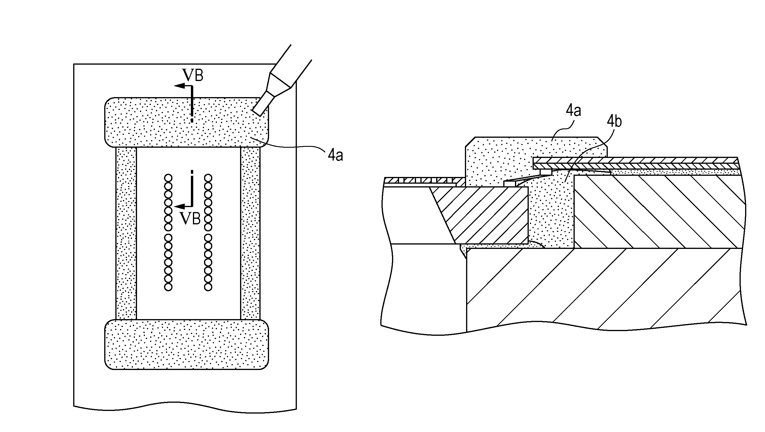
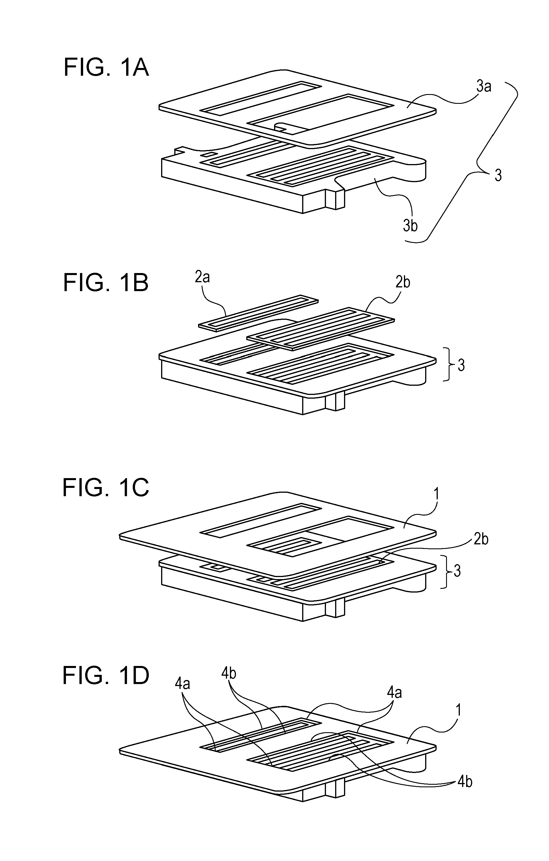
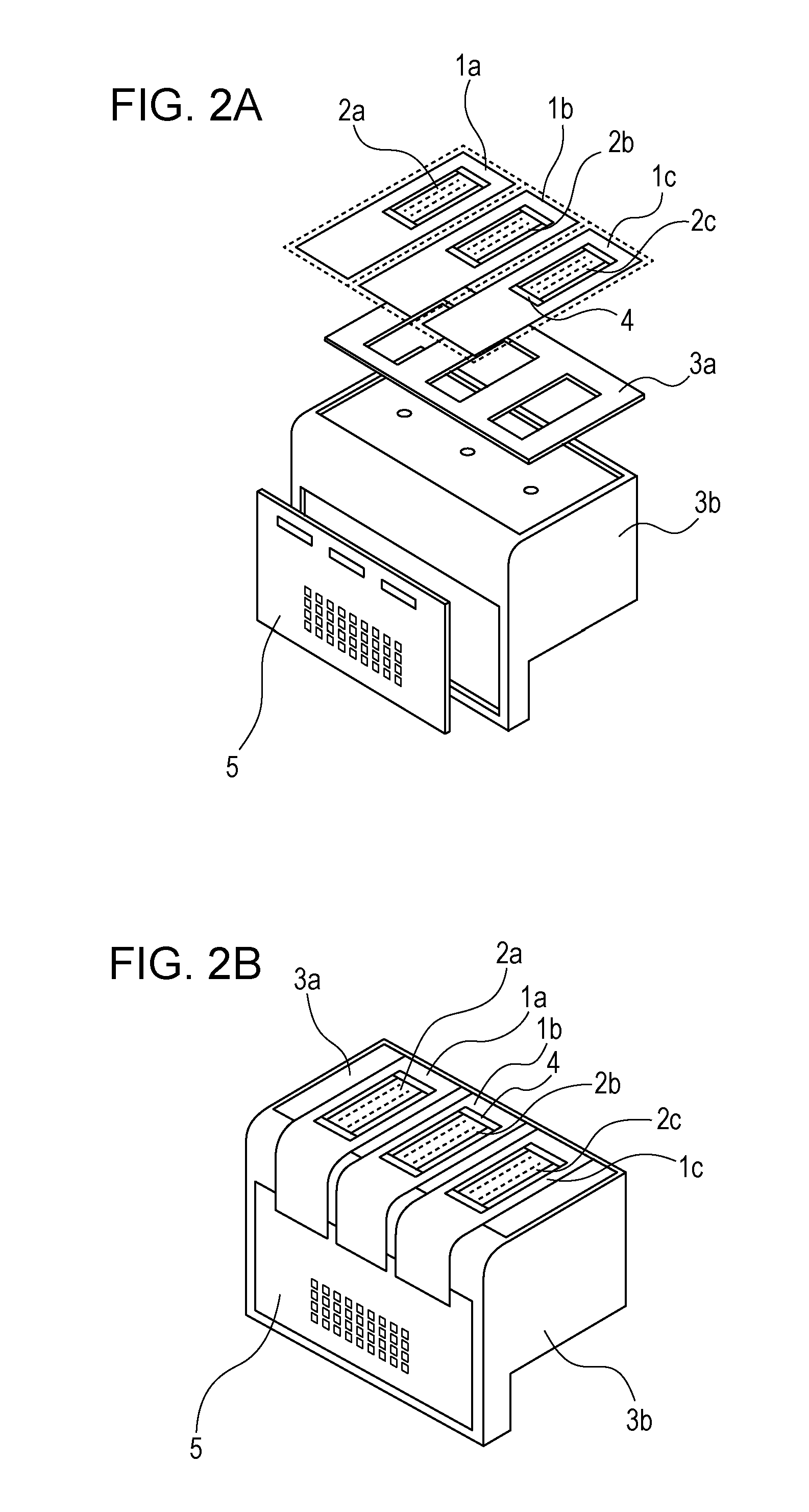
[0085]Inkjet recording heads of Examples 10 to 18 were fabricated in accordance with the first embodiment shown in FIGS. 3A to 5B. In Examples 10 to 18, the sealants used in Examples 1 to 9 shown in Table 1 were respectively used as the sealant 4a for sealing the upper side of the lead. Furthermore, CV5362 (trade name; manufactured by Panasonic Corp.) was used as the sealant 4b for sealing the lower side of the lead. In these Examples, the sealants were applied such that the thickness from the upper surface of the wiring substrate had the same value (400 μm). Each of the sealant on the upper side of the lead and the sealant on the lower side of the lead was irradiated with ultraviolet light immediately after application. The conditions for ultraviolet light irradiation for all were set at 150 mW / cm2×20 seconds. After confirming that the surface of the sealant on the upper side of the lead was cured, heating was performed at 150° C. for 3 hours.

[0086]In order to evaluate bond reliabi...


PUM

PropertyMeasurementUnit
thicknessaaaaaaaaaa
energyaaaaaaaaaa
activation energyaaaaaaaaaa

Abstract

A sealant contains a dicyclopentadiene type epoxy resin represented by formula 1 below, a hydrogenated bisphenol A epoxy resin, and a photo-induced cationic polymerization initiator, in which the content of the dicyclopentadiene type epoxy resin is 15 to 40 parts by mass relative to 100 parts by mass of the total mass of epoxy resins contained in the sealant.where n represents an integer of 0 to 2.

Description

BACKGROUND OF THE INVENTION[0001]1. Field of the Invention[0002]The present invention relates to a sealant, an inkjet recording head using a sealant, and a method for manufacturing the same.[0003]2. Description of the Related Art[0004]In an inkjet recording apparatus, recording is performed by ejecting ink from ejection ports toward recording paper. The inkjet recording apparatus generally includes an inkjet recording head that ejects ink from ejection ports and a supply member (supply system) that supplies ink to the recording head. The recording head generally includes an ejection element substrate, a wiring member, and a supporting member.[0005]Examples of a typical recording method using an inkjet recording apparatus include a method using electrothermal transducers. In this method, recording is performed on recording paper as described below. An electrothermal transducer is provided in a pressurizing chamber disposed in the vicinity of an ejection port of an ejection element su...

Claims


Application Information

Patent Timeline
Patent Type & Authority Patents(United States)
IPC IPC(8): C08L63/00H01R43/00C08G59/06C08G59/24C08L63/02C08G59/68B41J2/14
CPCC08G59/24C08L63/00C08G59/063C08G59/68Y10T29/49117B41J2/14072
Inventor HARADA, KOUJIIMAMURA, ISAOINAMOTO, TADAYOSHI
Owner CANON KK
Why Eureka
Try Eureka