
Nanostructure-film LCD devices

a technology of nanostructure films and display devices, applied in the field of nanostructure films, can solve the problems of insufficient solution, inferior flexibility, and the indium component of ito is rapidly becoming a scarce commodity, and achieves extraordinary strength and electrical conductivity, efficient heat conduction, and exceptional material properties.

Active Publication Date: 2014-11-11
SAMSUNG ELECTRONICS CO LTD
View PDF13 Cites 7 Cited by
  • Summary
  • Abstract
  • Description
  • Claims
  • Application Information

AI Technical Summary

Benefits of technology

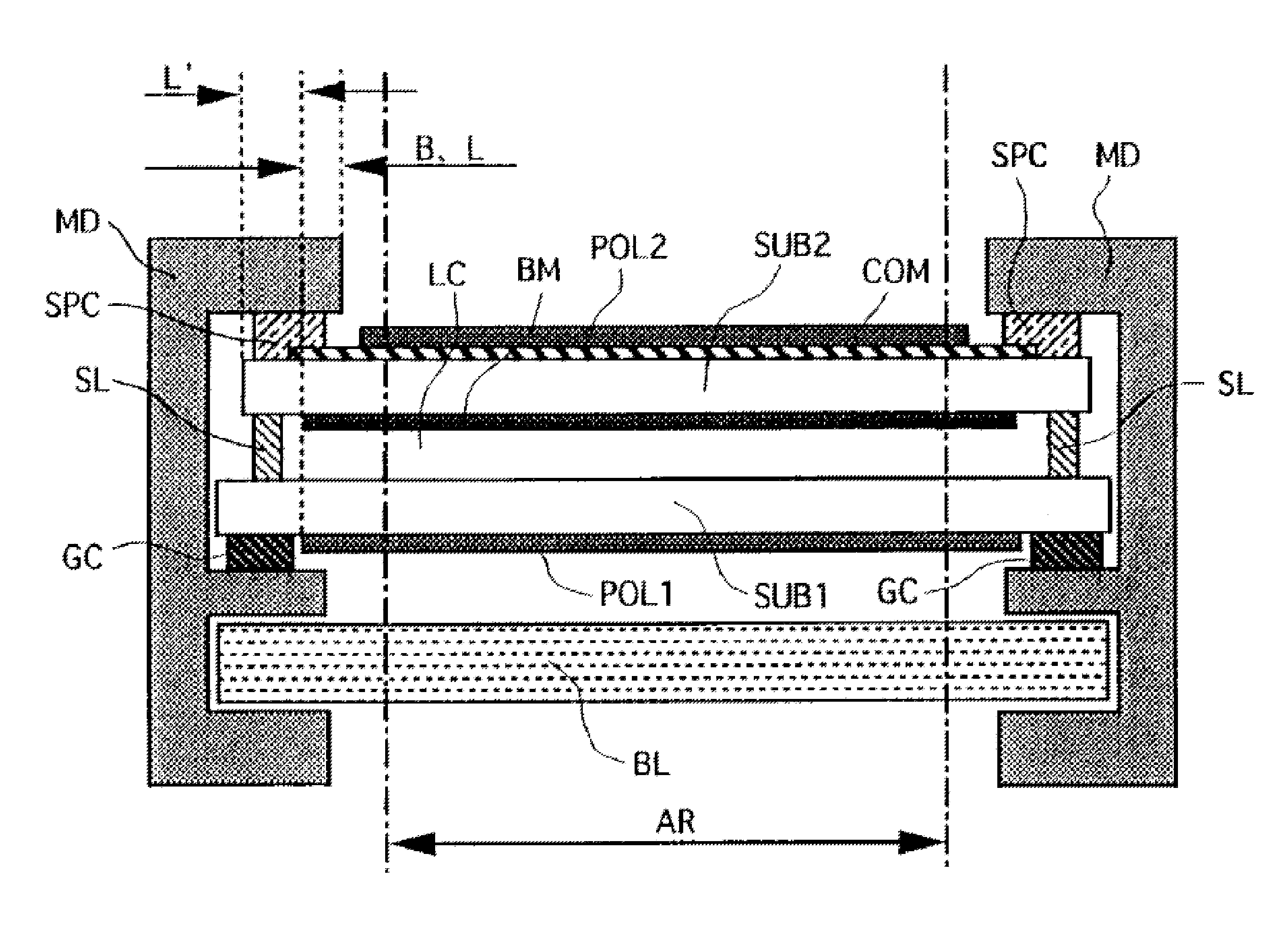
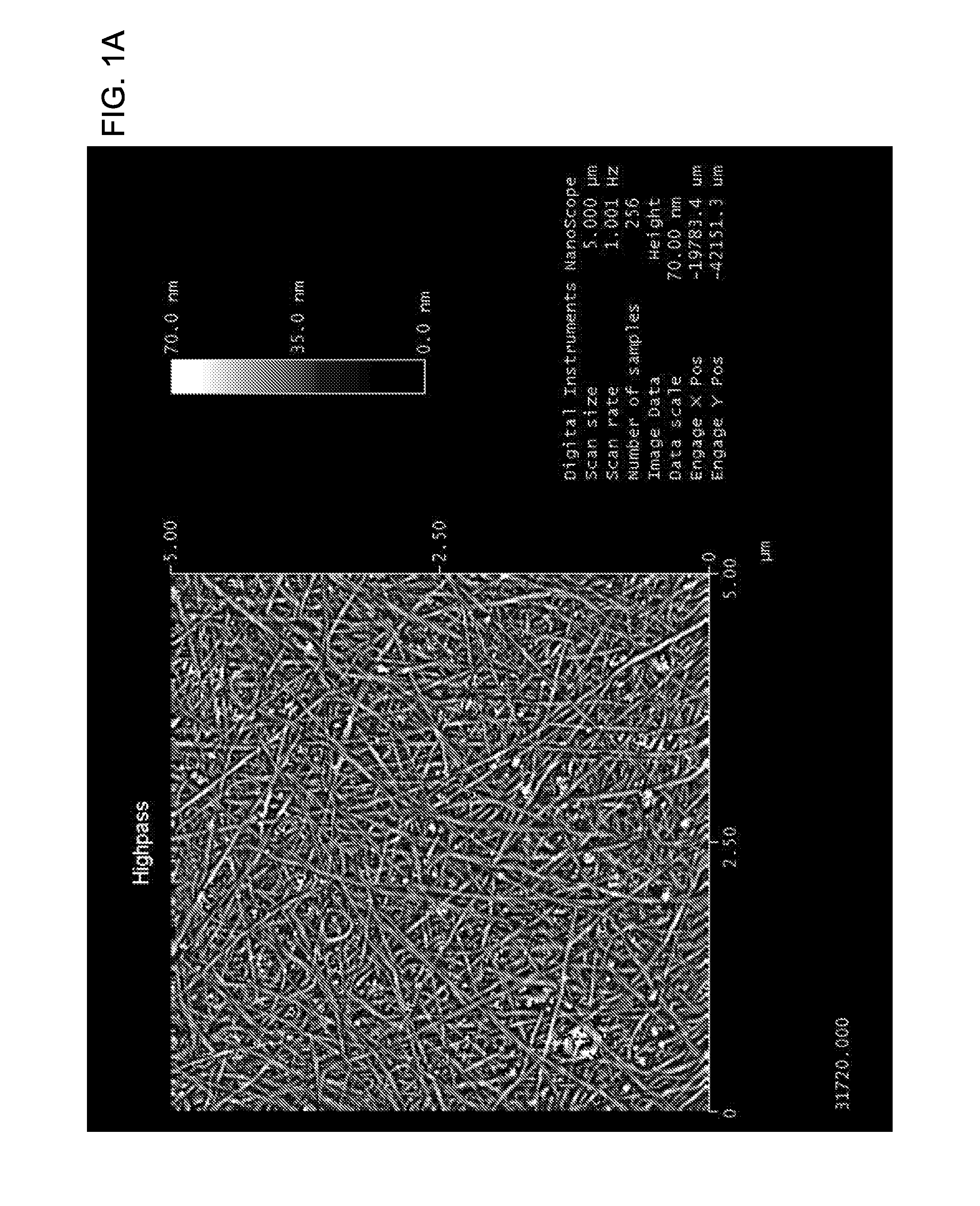
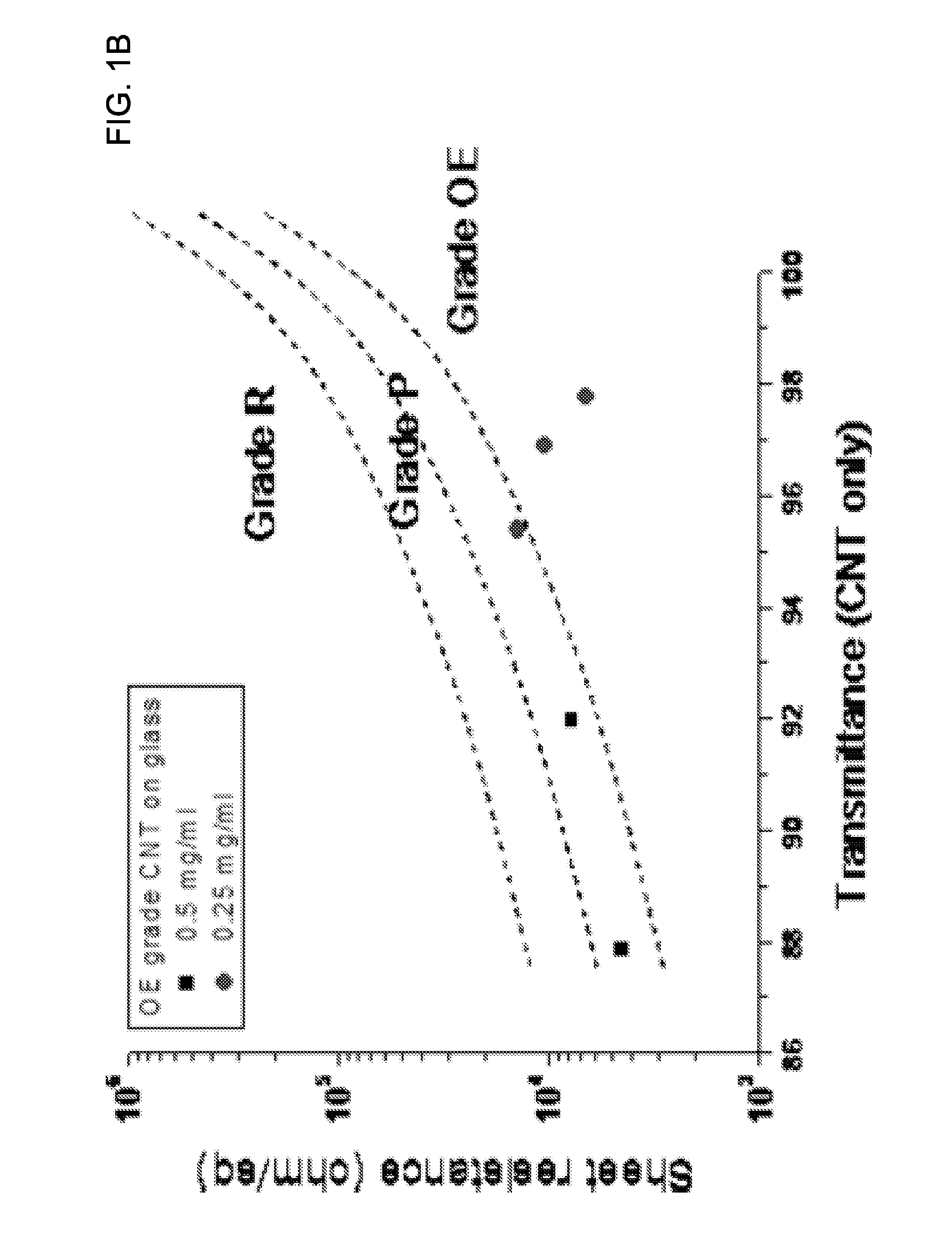
[0007]The present invention involves the use of nanostructure films in an in-plane switching (IPS) liquid crystal display (LCD) device. Nanostructures have attracted a great deal of recent attention due to their exceptional material properties. Nanostructures may include, but are not limited to, nanotubes (e.g., single-walled carbon nanotubes (SWNTs), multi-walled carbon nanotubes (MWNTs), double-walled carbon nanotubes (DWNTs), few-walled carbon nanotubes (FWNTs)), other fullerenes (e.g., buckyballs), graphene flakes / sheets, and / or nanowires (e.g., metallic (e.g., Ag, Ni, Pt, Au), semiconducting (e.g., InP, Si, GaN), dielectric (e.g., SiO2,TiO2), organic, inorganic). In one embodiment, nanostructure films may comprise at least one interpenetrating network of such nanostructures, and may similarly exhibit exceptional material properties. In another embodiment, a nanostructure film comprises at least one interconnected network of carbon nanotubes. In another embodiment, the nanostructures in the nanostructure film are in a medium, wherein the nanostructures are interconnected (e.g. the density of the nanostructures is above a percolation threshold in the medium). In another embodiment, a nanostructure film comprises at least one interconnected network of carbon nanotubes and can exhibit extraordinary strength and electrical conductivity, as well as efficient heat conduction and substantial optical transparency.
[0008]In one embodiment of the present invention, an LCD device comprises an electrically conductive and optically transparent nanostructure film deposited adjacent to or forming a part of at least one of a) a layer comprising triacetyl cellulose (TAC), b) a polarizing layer, c) an adhesive layer, d) a protective layer, e) an anti-glare layer f) an anti-reflective layer, or g) an antistatic layer. In another embodiment, the nanostructure film of the LCD device serves a shielding function against static electricity.
[0012]In another embodiment, the nanostructure film of the IPS LCD is patterned. In another embodiment, the nanostructure film of the IPS LCD comprises nanostructures, wherein the nanostructures are aligned. In another embodiment, the nanostructure film of the IPS LCD comprises nanostructures, wherein the nanostructures provide an optical polarizing effect.
[0013]In another embodiment, the upper polarizer plate of the IPS LCD comprises nanostructure film comprising nanostructures, wherein the nanostructures provide an optical polarizing effect.

Problems solved by technology

However, ITO can be an inadequate solution for many of the above-mentioned applications (e.g., due to its relatively brittle nature, and correspondingly inferior flexibility and abrasion resistance, especially at low thicknesses), and the indium component of ITO is rapidly becoming a scarce commodity.
Additionally, ITO deposition usually requires expensive, high-temperature sputtering, which can be incompatible with many device process flows.

Method used


Image

  • Nanostructure-film LCD devices
  • Nanostructure-film LCD devices
  • Nanostructure-film LCD devices

Examples


Embodiment Construction

[0032]In one embodiment, an electrically conductive and optically transparent nanostructure film, for example as described above, may be employed in an in-plane switching (IPS) LCD device to serve a shielding function against static electricity. The IPS LCD device may include a switching element, a pixel electrode and a counter electrode formed in a unit pixel over a first substrate of two substrates which are so disposed as to be opposed to each with a liquid crystal layer provided there between and at least one of the two substrates is transparent, and the light that passes through the liquid crystal layer is modulated with an electric field generated between the pixel electrode and the counter electrode substantially in parallel with the first substrate; wherein a black matrix having a resistivity of not smaller than 106 ohm-cm is formed between the first substrate and the second substrate, and an electrically conductive and optically transparent nanostructure film is formed over...


PUM

PropertyMeasurementUnit
semi-transparentaaaaaaaaaa
sheet resistanceaaaaaaaaaa

Abstract

This invention relates to an LCD device comprising an electrically conductive and optically transparent nanostructure film deposited adjacent to or forming a part of at least one of a) a layer comprising triacetyl cellulose (TAC), b) a polarizing layer, c) an adhesive layer, d) a protective layer, e) an anti-glare layer f) an anti-reflective layer, or g) an antistatic layer. One embodiment is a device comprising an in plane switching (IPS) liquid crystal display (LCD) and a nanostructure film, wherein the film is electrically conductive, and wherein the film is optically transparent.

Description

CROSS-REFERENCES TO RELATED APPLICATIONS[0001]This patent application claims priority from U.S. provisional application Ser. No. 60 / 983,537, filed Oct. 29, 2007, and Ser. No. 61 / 039,852, filed Mar. 27, 2008, which applications are incorporated herein by reference.FIELD OF THE INVENTION[0002]The present invention relates generally to nanostructure films, and more specifically to nanostructure films employed in display devices.BACKGROUND OF THE INVENTION[0003]Many modern and / or emerging applications require at least one device electrode that has not only high electrical conductivity, but high optical transparency as well. Such applications include, but are not limited to, touch screens (e.g., analog, resistive, 4-wire resistive, 5-wire resistive, surface capacitive, projected capacitive, multi-touch, etc.), displays (e.g., flexible, rigid, electro-phoretic, electro-luminescent, electrochromatic, liquid crystal (LCD), plasma (PDP), organic light emitting diode (OLED), etc.), solar cell...

Claims


Application Information

Patent Timeline
Patent Type & Authority Patents(United States)
IPC IPC(8): G02F1/1343G02F1/1335
CPCG02F1/134363G02F2202/22G02F1/133502G02F1/133528Y10T428/1036C09K2323/03
Inventor PARK, YOUNG-BAE
Owner SAMSUNG ELECTRONICS CO LTD
Learn More