Machine tool component and method for producing the machine tool component

Pending Publication Date: 2022-11-03
HAIMER
View PDF0 Cites 0 Cited by
  • Summary
  • Abstract
  • Description
  • Claims
  • Application Information

AI Technical Summary

Problems solved by technology

However, a larger, and usually stiffer, diameter in turn results in a higher mome

Method used


Image

  • Machine tool component and method for producing the machine tool component

Examples


Embodiment Construction

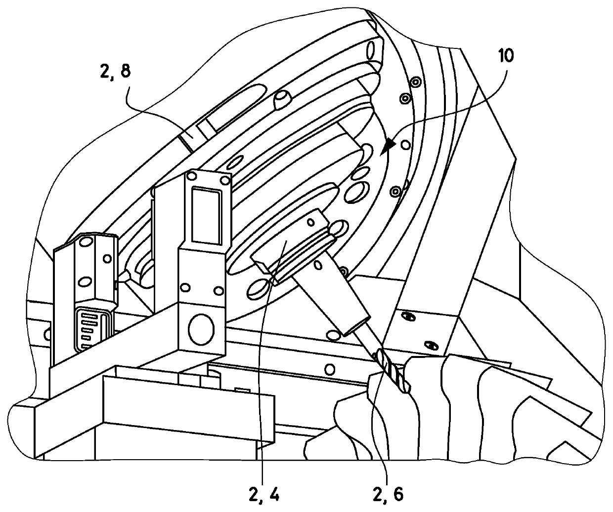
[0057]Referring now to the single FIGURE of the drawing in detail, there is shown is shown a portion of a machine tool 10, in this case a milling machine 10, in the case of blisk machining.

[0058]As shown in the FIGURE, the milling machine 10 provides a spindle 8 (only a portion of which is visible), a tool holder 4, in this case a shrink-fit chuck 4, and a tool 6, in this case a cutter 6.

[0059]A particular feature of the milling machine 10 is that its components, in this case the spindle 8, the shrink-fit chuck 4, and the cutter 6, consist of amorphous metal (whereas these components otherwise do not differ from their known and usual structure and form).

[0060]The components have here been manufactured from a zirconium-based alloy with a proportion (by weight) of zirconium of 74% and further proportions (by weight) of copper (17%), aluminum (3%), nickel (2%), titanium (2%), and niobium (2%).

[0061]Whereas the spindle 8 and the cutter 6 have been injection-molded, the shrink-fit chuck ...


PUM


Abstract

In order to improve a usage of machine tool components, it is provided that the machine tool component is formed at least partially, in particular essentially, or alternatively completely from an amorphous metal. It is provided that the tool component is produced using injection molding or 3D printing or plastic deformation.

Description

CROSS-REFERENCE TO RELATED APPLICATION[0001]This application claims the priority, under 35 U.S.C. § 119, of German Patent Application DE 10 2021 111 186.2, filed Apr. 30, 2021; the prior application is herewith incorporated by reference in its entirety.FIELD AND BACKGROUND OF THE INVENTION[0002]As is known, machine tools are machines for manufacturing workpieces by means of (power-operated) tools, the movement of which relative to one another is predetermined by the machine. The most important examples of such machine tools here include turning and milling machines with the appropriate (power-operated) tools such as turning tools and milling tools.[0003]Such machine tools have numerous components, the best known, in particular of such known turning and milling machines, being spindles, tool holders, and the (power-operated) tools, wherein they are all, also via standard interfaces, connected to one another in the movement chain of the machine tool or the turning / milling machine.[000...

Claims


Application Information

Patent Timeline
IPC IPC(8): B23B31/02
CPCB23B31/02B33Y80/00B22F3/225C22C45/00C22C1/0458B22F10/20B22F10/25B22F10/38B22F1/08C22C2200/02C22C45/10C22C45/001C22C45/02B23B2222/56B23B2228/00
Inventor HAIMER, FRANZ
Owner HAIMER
Why Eureka
Try Eureka