Conversion structure, image sensor assembly and method for fabricating conversion structure

a conversion structure and image sensor technology, applied in the field of electrical wave sensor assemblies, can solve the problems of poor light conversion efficiency, inability to mix tl and csi uniformly, and expensive waste gas filtration systems, and achieve the effects of low light conversion efficiency, easy determination by light sensor devices, and low cos

Inactive Publication Date: 2014-11-18
ARCHITEK MATERIAL
View PDF15 Cites 3 Cited by
  • Summary
  • Abstract
  • Description
  • Claims
  • Application Information

AI Technical Summary

Benefits of technology

[0008]To this end, one purpose of the present invention is to provide a conversion structure, an image sensor assembly and a method for fabricating a conversion structure that overcome the drawbacks caused by using CsI:Tl as scintillator.
[0012]The present invention provides a conversion structure, an image sensor assembly and a method for fabricating a conversion structure. Since the currently used epitaxial growth processes and toxic materials are all replaced in the present invention, the corresponding process can be more convenient and eco-friendly. In addition, owing to the specific geometric design of the conversion structure trench and the existence of the reflective film and the reflective layer, the intensity of light having a second wavelength and outputted from the conversion structure into the light sensor assembly can be increased accordingly. In this way, the change in light intensity can be determined by the light sensor devices more easily so as to overcome the drawbacks usually associated to CsI:Tl, such as relatively low light conversion efficiency.

Problems solved by technology

However, there are many drawbacks when using scintillators as main active components in the X-rays image sensor assemblies.
For example, in order to prevent toxic heavy metals, i.e. Tl, from causing environmental pollution and from negatively affecting human health, expensive waste gas filtration systems are required for the process of manufacturing the scintillator.
Furthermore, Tl and CsI can not be mixed uniformly due to their inherent material properties.
That is to say, Tl is unevenly distributed within CsI:Tl and causes bad light conversion efficiency.

Method used


Image

  • Conversion structure, image sensor assembly and method for fabricating conversion structure
  • Conversion structure, image sensor assembly and method for fabricating conversion structure
  • Conversion structure, image sensor assembly and method for fabricating conversion structure

Examples


Embodiment Construction

[0021]In the following description, numerous specific details are given to provide a thorough understanding of a conversion structure, an image sensor assembly and a method for fabricating a conversion structure related to the invention. It will, however, be apparent to one skilled in the art that the invention may be practiced without these specific details. Furthermore, some well-known system configurations and process steps are not disclosed in detail, as these should be well-known to those skilled in the art.

[0022]Likewise, the drawings showing the embodiments of the apparatus are not to scale and some dimensions are exaggerated for clarity of presentation. Also, when multiple embodiments are disclosed and described as having some features in common, like or similar features will usually be described with same reference numerals for ease of illustration and description thereof.

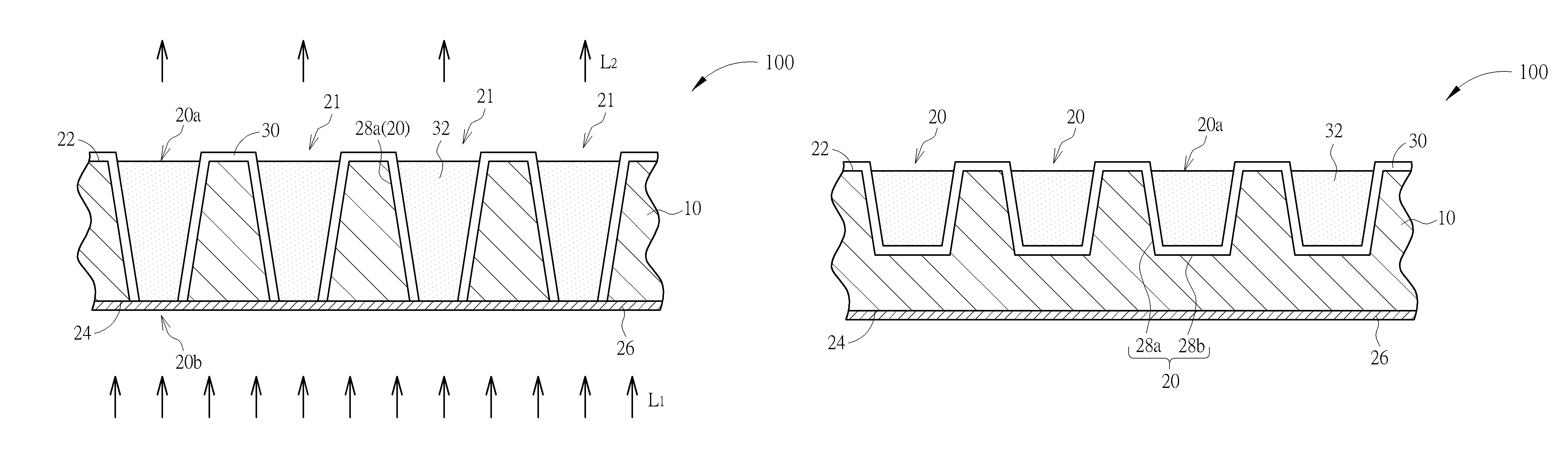
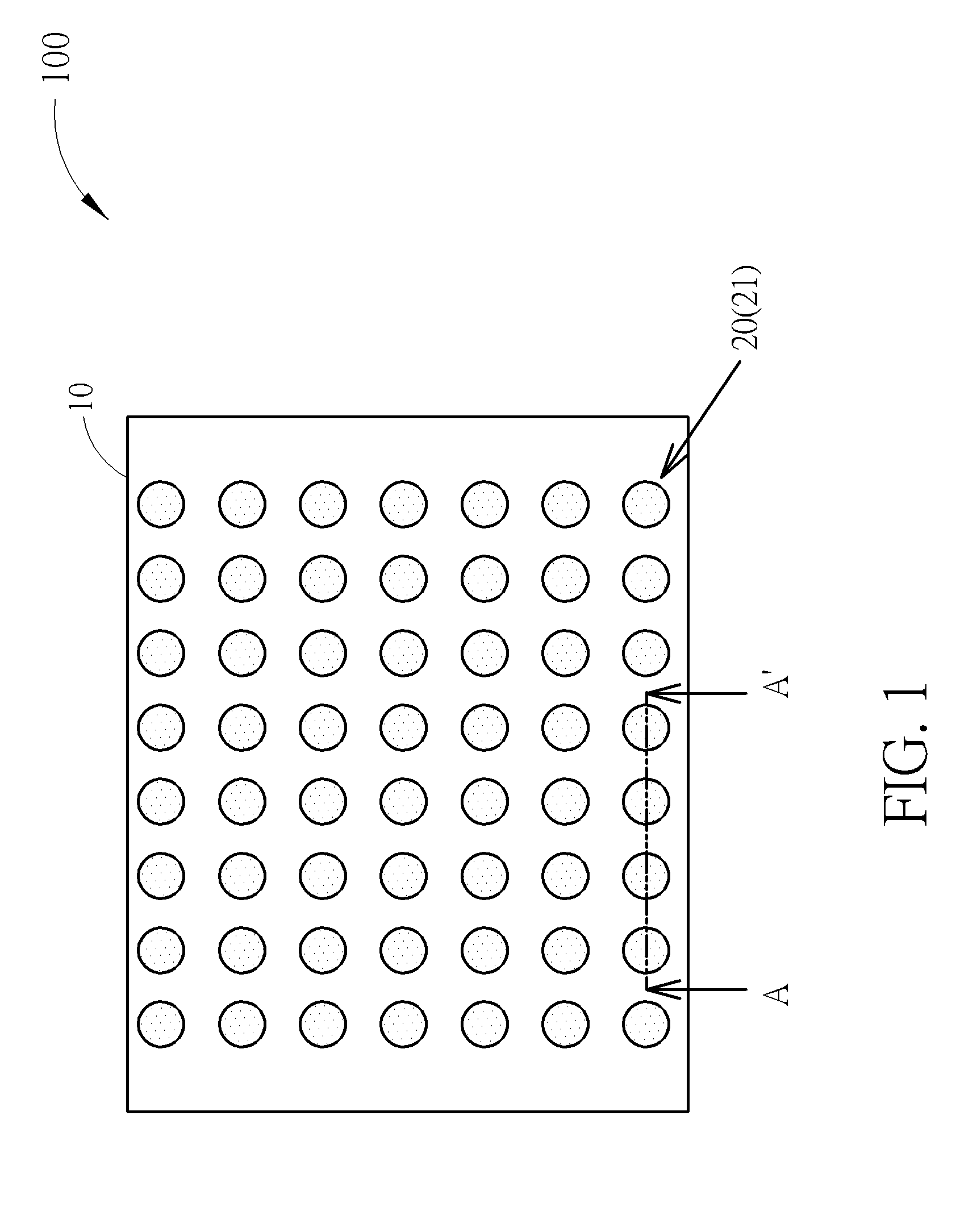
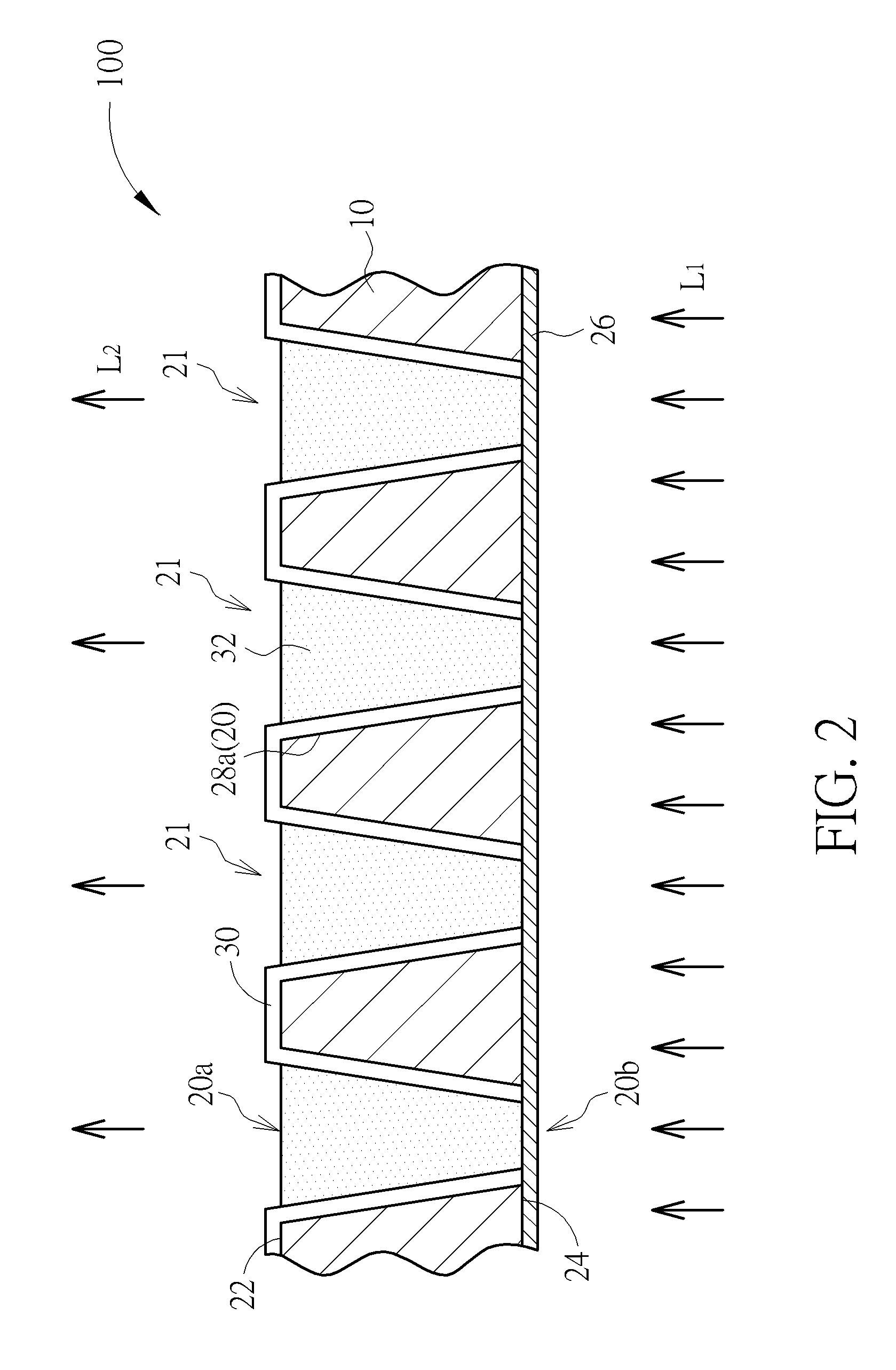
[0023]Please refer to FIG. 1 and FIG. 2. FIG. 1 is a schematic top view showing a conversion structure ...


PUM


Abstract

An electromagnetic wave conversion structure consists of a substrate, a plurality of electromagnetic wave conversion units forming a two-dimensional array, a reflective film and a plurality of reflective layers. The substrate has a first surface and a second surface disposed opposite to the first surface. The second surface consists of a plurality of trenches formed in the body of the substrate. Each electromagnetic wave conversion units is disposed in each trench, is used to absorb first electromagnetic waves with a first wavelength and is used to emit second electromagnetic waves with a second wavelength. The first wavelength is shorter than the second wavelength. The reflective film covers the first surface of the substrate and is used to reflect the second electromagnetic wave. Each of the reflective layers is disposed on the sidewall of each trench of the corresponding electromagnetic wave conversion unit.

Description

BACKGROUND OF THE INVENTION[0001]1. Field of the Invention[0002]The present invention generally relates to the field of electromagnetic wave sensor assemblies, and more particularly, to a conversion structure, an image sensor assembly and a method of fabrication a conversion structure.[0003]2. Description of the Prior Art[0004]With the advent of the aging society, the focus on the development of methods for preventive medicare has attracted much attention, especially to the development of equipments for medical diagnostic imaging due to its high technical threshold, high value-added benefit and non-invasive properties. Generally, the types of the medical diagnostic imaging equipments include X-rays systems, electrocardiography (ECG) systems, ultrasonic diagnostic systems, computed tomography (CT) systems, magnetic resonance imaging (MRI) systems, and so forth. Among these types of equipments, X-ray and computed tomography systems are widely used in various medical fields, such as de...

Claims


Application Information

Patent Timeline
Patent Type & Authority Patents(United States)
IPC IPC(8): H01L33/00H01L31/0232
CPCH01L31/02327H01L31/085G01T1/2002H01L31/02322
Inventor HO, SHU-LINTANG, PAO-YUNYANG, KEI-HSIUNG
Owner ARCHITEK MATERIAL
Why Eureka
Try Eureka