Power transmitting apparatus

a power transmission and apparatus technology, applied in the direction of gearing details, hoisting equipment, gearing, etc., can solve the problems of undercutting, gear rattle during reverse motion, noise or vibration, etc., and achieve the effect of reducing the thickness of the tooth and sufficient tooth contact ra

Active Publication Date: 2014-11-25
SEJIN IGB
View PDF36 Cites 8 Cited by
  • Summary
  • Abstract
  • Description
  • Claims
  • Application Information

AI Technical Summary

Benefits of technology

[0022]The present invention provides a power transmitting apparatus in which a cycloid tooth shape having a tooth size higher than a trochoid tooth shape and capable of maintaining a sufficient tooth contact rate is applied to a tooth shape of a tooth gear engagingly coupled to a pin gear capable of relatively moving so that a pin stuck phenomenon and reduction of a tooth thickness due to the undercut of a tooth root portion may be solved.

Problems solved by technology

However, when the backlash is formed as illustrated in FIG. 2, transfer or a motion is not smoothly performed, that is, a motion is transferred intermittently from the tooth J2 to the tooth J4, so that noise or vibration is generated.
Further, the gears may rattle during a reverse motion.
However, in the tooth J2 of the rack J1 according to the cycloid curve, when the pin J5 arrives at a tooth root J6, a radius of curvature of a central track of the pin J5 becomes zero so that, during the processing of the part of the rack J1, an undercut A such as a hatched portion in FIG. 4 may be problematic.
However, as illustrated in FIG. 5, it may be problematic when the undercut A is applied to an apparatus requiring high precision such as a precision mechanism because the pin J5 escapes from the tooth J2 of the rack J1 and does not follow a predetermined cycloidal track, thus failing to transfer a torque.
Further, as the escape and engagement of the pin J5 with respect to the tooth J2 of the rack J1 due to the undercut A, noise and vibration are generated so that life span of a tooth surface may be deteriorated.
In particular, when a pre-load is applied between the rack J1 and the pinion J3 after removing backlash to improve rigidity, the above-described problem is severely generated.
Also, in this area, a backlash in forward and reverse directions is inevitably generated, which has been disregarded until now.
In particular, the bump and release causes fatigue of the pin J5 or the tooth J2 so that life span of the rack and pinion may be deteriorated.
However, the trochoid tooth shape may have problems that reduction of a tooth size (tooth width and tooth height), reduction of a tooth shape contact rate due to reduction of a power transfer area of one tooth, remarkable deterioration of rigidity due to reduction of thickness in a tooth root portion, and shortening of life span of a pin support bearing due to an increase in a normal force applied to each pin gear during the application of the same torque due to a decrease of a pitch diameter of a pin gear by electrostatic potential.

Method used


Image

  • Power transmitting apparatus
  • Power transmitting apparatus
  • Power transmitting apparatus

Examples


first embodiment

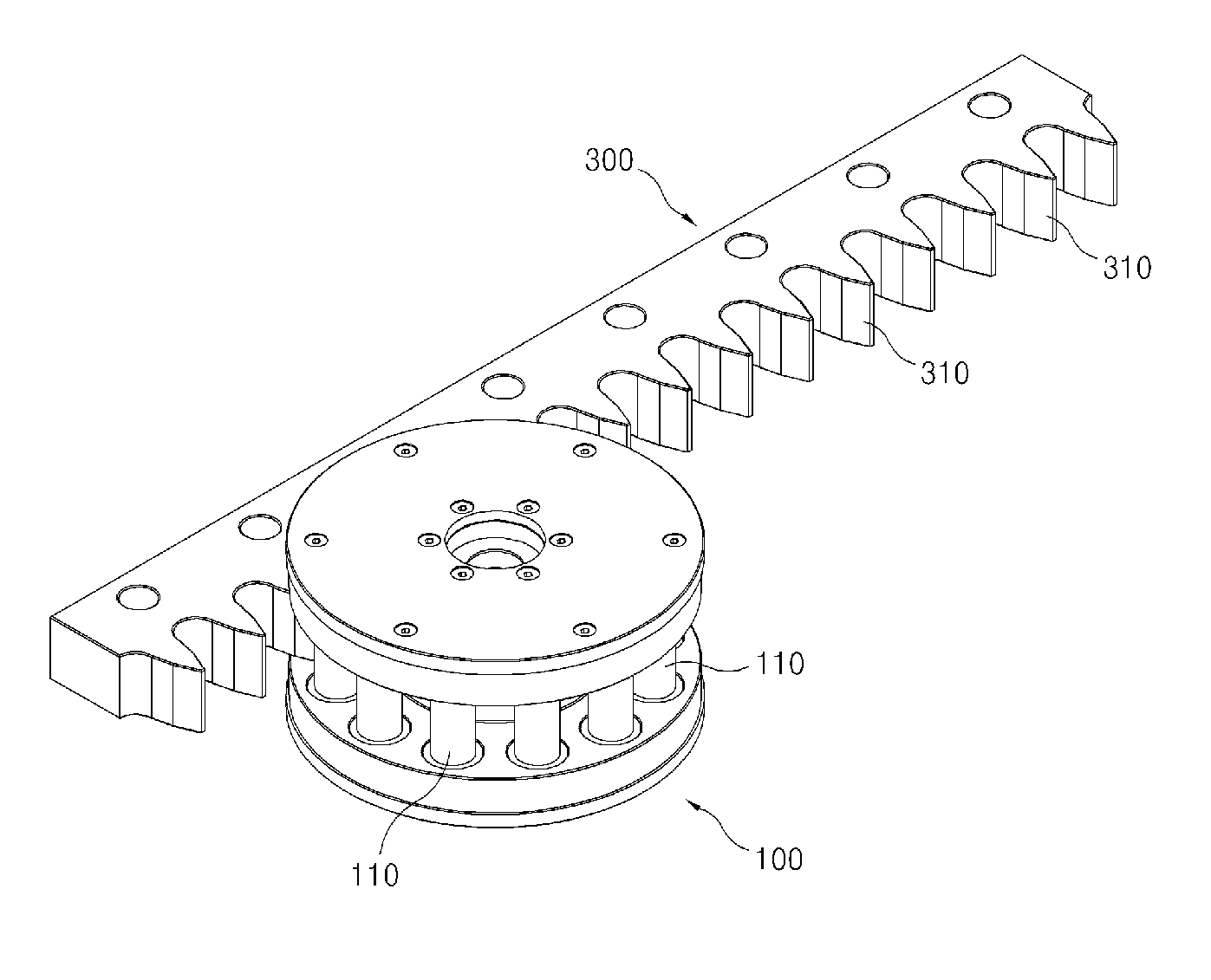
[0057]FIG. 7 is a perspective view of a power transmitting apparatus according the present invention. FIG. 8 is a side view of FIG. 7. FIG. 9 is an enlarged view of a major part of FIG. 8. FIG. 10 is an exploded perspective view of the pin gear of FIG. 7.

[0058]Referring to FIGS. 7-10, a power transmitting apparatus according to the present embodiment includes a pin gear 100 having a plurality of pins 110 capable of performing a rolling motion and a tooth gear 300 having a plurality of teeth 310 and engagingly coupled to the pin gear 100 to be capable of relatively moving.

[0059]In the present embodiment, the pin gear 100 is a pinion-type driving gear and the tooth gear 300 is a rack-type driven gear. That is, as the pin gear 100 to which a motor (not shown) is connected performs a rotational motion, the tooth gear 300 engaged with the pin gear 100 performs a linear motion, thereby forming a power transmitting system. However, the right scope of the present invention is not limited th...

second embodiment

[0083]FIG. 11 is a perspective view of a power transmitting apparatus according the present invention. FIG. 12 is a perspective view of a power transmitting apparatus according a third embodiment of the present invention.

[0084]In the second and third embodiments, like in the first embodiment, the pin gear 100 is a pinion-type driving gear and tooth gears 300a and 300b are rack-type driven gears. However, in the second and third embodiments, the tooth gears 300a and 300b have a curved shape unlike the above-described embodiment.

[0085]In FIG. 11, the tooth gear 300a having a curved shape is inscribed on the pin gear 100. In FIG. 12, the tooth gear 300b having a curved shape is circumscribed on the pin gear 100. In these cases, as the pin gear 100 to which a motor (not shown) is connected performs a rotational motion, the tooth gears 300a and 300b engaged with the pin gear 100 performs a linear motion, thereby forming a power transmitting system.

[0086]In the structures of FIGS. 13-16, ...


PUM


Abstract

Disclosed is a power-transmitting apparatus. A power-transmitting apparatus of the present invention comprises: a pin gear provided with a plurality of pins capable of rolling movement; and a spur gear provided with a plurality of teeth and en-gagingly coupled to the pin gear so as to be relatively movable, wherein the spur gear teeth are formed with a cycloid tooth shape, and a polygonal tooth root space is formed at a tooth root region of the spur gear. As compared to a trochoid tooth shape, the tooth shape of the spur gear engagingly coupled to the pin gear so as to be relatively movable according to the present invention has a greater tooth size so that it can be applied as a cycloid tooth shape capable of maintaining a sufficient tooth contact ratio, and can resolve a reduction in tooth thickness and the wedging of the pins from an undercut at the tooth root region.

Description

TECHNICAL FIELD[0001]The present invention relates to a power transmitting apparatus, and more particularly, to a power transmitting apparatus in which a cycloid tooth shape having a tooth size higher than a trochoid tooth shape and capable of maintaining a sufficient tooth contact rate is applied to a tooth shape of a tooth gear engagingly coupled to a pin gear capable of relatively moving so that a pin stuck phenomenon and reduction of a tooth thickness due to the undercut of a tooth root portion may be solved.BACKGROUND ART[0002]A power transmitting apparatus is largely divided into a rack and pinion for converting a rotational motion to a linear motion or vice versa and a gear train for transmitting only a rotational motion while converting a rotational speed and a torque. Typically, a power transmitting system of a power transmitting apparatus mainly uses a tooth shape according to an involute curve principle. However, there is a rare case of using a tooth shape according to a ...

Claims


Application Information

Patent Timeline
Patent Type & Authority Patents(United States)
IPC IPC(8): F16H55/26F16H19/04F16H55/10F16H57/04
CPCF16H19/04F16H55/10F16H55/26Y10T74/18808Y10T74/19656Y10T74/18768F16H1/24
Inventor LIM, SUN, HO
Owner SEJIN IGB
Why Eureka
Try Eureka