Hemodialysis catheter assembly

a technology of hemodialysis and catheter, which is applied in the field of medical devices, can solve the problems of large vein distension and growth, high speed of blood rushing out of the open end of the catheter, and inability to substitute, so as to prevent blood flow through the tubing

Active Publication Date: 2015-01-06
DIALYSFLEX
View PDF23 Cites 13 Cited by
  • Summary
  • Abstract
  • Description
  • Claims
  • Application Information

AI Technical Summary

Benefits of technology

[0022]In a second embodiment of the invention, the pinch means comprises a pinch bar that is mounted and movable within the housing between an extended position and a retracted position. In the extended position, the bar engages an exterior surface of the collapsible tubing with sufficient force to collapse the tubing, occlude the lumen thereof, and thereby prevent blood flow through the tubing; whereas, in the retracted position, the pinch bar is disengaged from the collapsible tubing, the tubing is not collapsed, the lumen of the tubing is not occluded, and blood can flow through the collapsible tubing.

Problems solved by technology

This causes high pressure arterial blood to pour into a normally low pressure vein, which causes the vein to distend and grow much larger.
But, as a practical matter, such a substitution cannot be done because of the difference in the pressure of the blood at an intravenous access site compared to the pressure of the blood at a hemodialysis access site that connects to the arterial side of the patient's blood circulatory system, because the arterial side has relatively high blood pressure—i.e., five to six times higher than an intravenous access site.
If one attempts to use an intravenous catheter as a hemodialysis catheter, the higher pressure encountered on the arterial side of a patient's blood circulatory system will cause blood to rush out from the open end of the catheter at high speed.
This would obviously create a hazard for the healthcare workers, exposing them unnecessarily to the patient's blood and to possible contamination by blood-borne pathogens.
Furthermore, patients who receive dialysis therapy are predisposed to a condition that limits their ability to produce red blood cells.
The pressures within the lumen of the catheter would be too great to be overcome by such a simple mechanical procedure.
They are artificially made avenues of high pressure blood flow created surgically just beneath the surface of the skin, and as such they are far more prone to clotting, and therefore to ruin, than′ any naturally formed blood vessel.
The above-referenced devices of Moorehead and of Harding et al. are not really suitable for use in hemodialysis because they fail to adequately address the problem of turbulence in blood flowing at high speed and under high pressure through the relatively small internal channel (lumen) within a dialysis catheter.
Excessive turbulence can cause red blood cells to break open, rendering them useless to the patient and possibly contributing to electrolyte imbalances within the blood stream.
The failure of such a probe to join flush with this window will cause the inserted end of the probe to be exposed as an open step or open shelf within the lumen of the dialysis catheter.
Blood rushing past this exposed shelf at high speed will be subjected to excessive turbulence.
Similarly, all five versions of the device disclosed by Moorehead fail to adequately address the problem of excessive turbulence.
Such systems of narrow channels create excessively turbulent flow of blood through the lumen of a catheter under the high pressure, high speed flow conditions encountered at a hemodialysis access site.
Furthermore, such systems of channels create high back pressure that slows the progress of filtration and circulation in a dialysis machine circuit.
Hard pressure applied to the button causes hard pressure to be applied over the surface of the hemodialysis access site.
That is an unacceptable practice, as it is well known that such hard pressure can lead to complications with the access site itself.
The thin, dual membrane septum assembly disclosed by Harding et al., which is intended to permit blood flow in one direction only, is likely to weaken with use and begin to deform to permit blood flow in an opposite direction through the septum assembly.

Method used


Image

  • Hemodialysis catheter assembly
  • Hemodialysis catheter assembly
  • Hemodialysis catheter assembly

Examples


Embodiment Construction

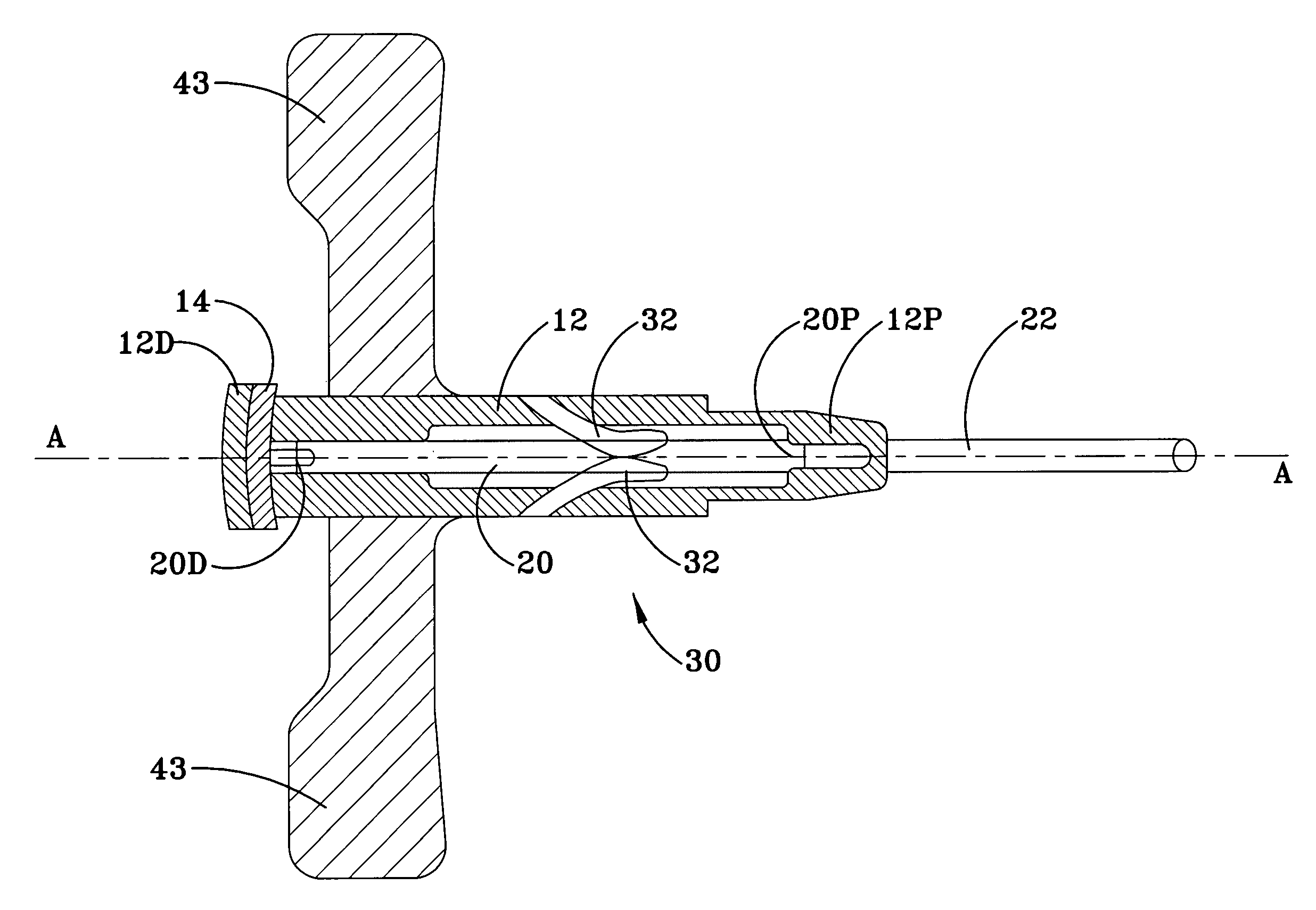
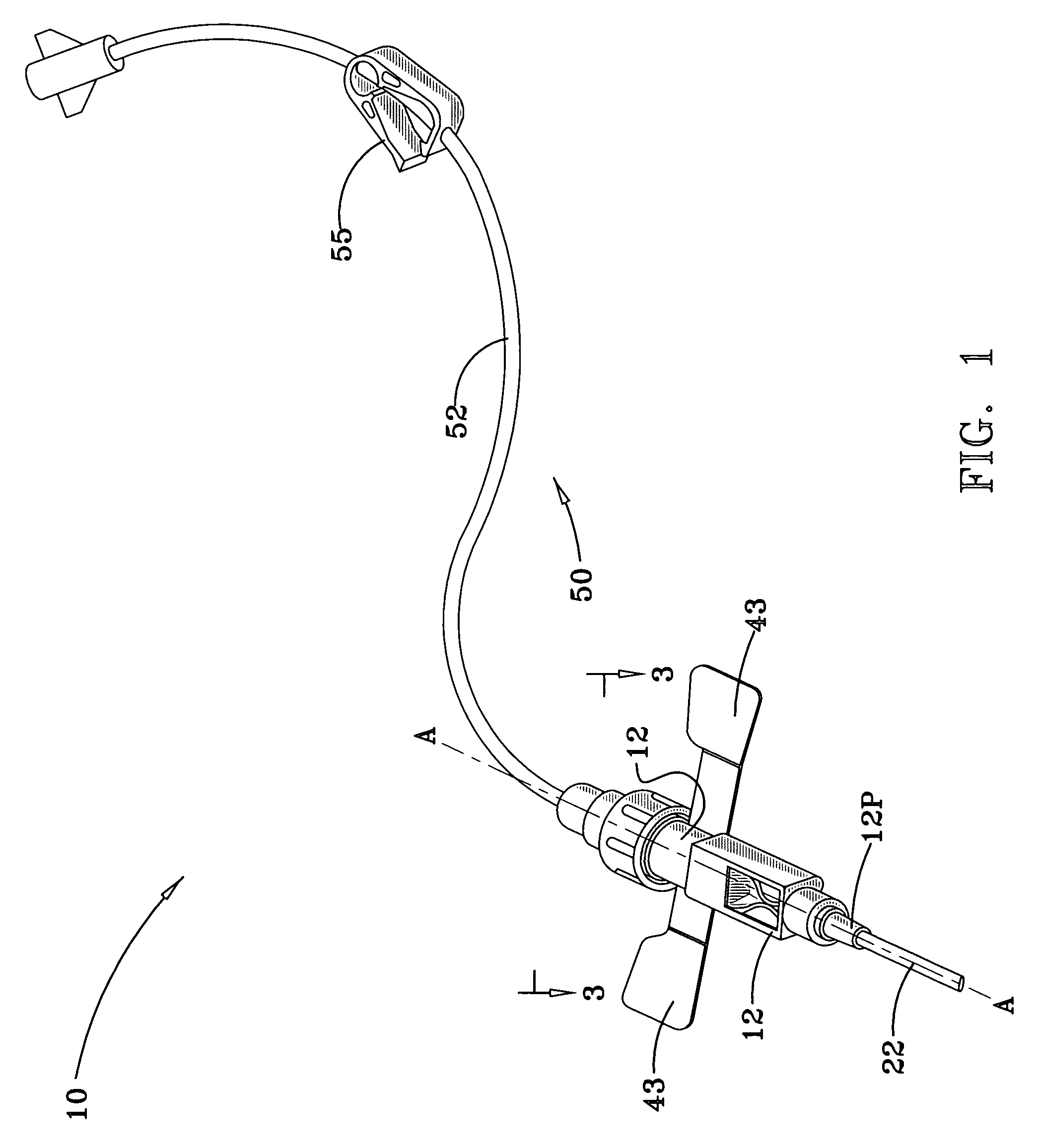
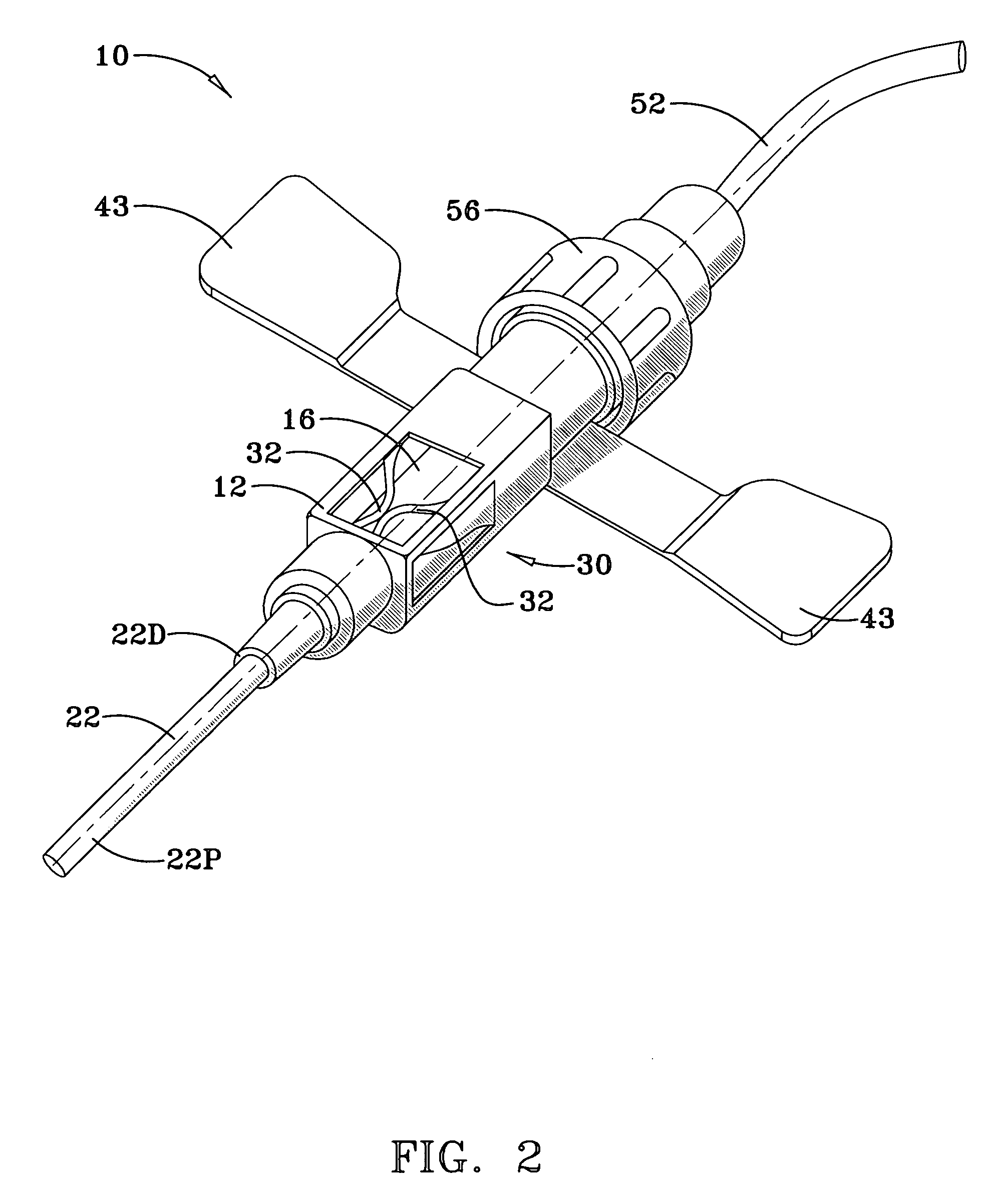
[0044]A first embodiment of the present invention will be described hereinafter with respect to the drawings. Throughout the description of this first embodiment, as well as of the other embodiments of the invention discussed below, the term “proximal” when applied to some component or aspect of the invention should be understood to mean that the component or aspect of the invention is relatively near to a patient's hemodialysis access site when the invention is in use, and the term “distal” should be understood to mean it is relatively remote from said site. FIG. 1 depicts a hemodialysis catheter assembly according to the first embodiment of the invention, denoted generally by the numeral 10, its sterile packaging (not shown) having been removed, and ready for use in hemodialysis. With further reference to FIGS. 2-9, it may be seen that the assembly 10 includes a housing 12 that extends along a longitudinal axis A-A from an open, proximal end 12P to an opposite, open, distal end 12...


PUM


Abstract

A hemodialysis catheter assembly with a flexible catheter lead that can control blood flow at a hemodialysis access site even under high blood pressures encountered at such sites. Flexible tubing extends through the hollow interior of a housing having opposite, open ends. The assembly includes components to alternately occlude or not occlude the lumen of the flexible tubing. In a first embodiment, spring clips press against the tubing, but insertion of a hollow sleeve into the lumen thereof retracts the clips and provides a flow path. In a second embodiment, a pinch bar can be manually moved into and out of engagement with the flexible tubing to occlude or open a flow path. In a third embodiment, the housing has a screw cap. A spring-loaded pinch bar presses against, and occludes the lumen of, the collapsible tubing when the screw cap is screwed into a threaded cutout in the housing, and provides a flow path through the tubing when the screw cap is removed. In a fourth embodiment, the tang portion of a tongue when in an extended position presses against, and occludes the lumen of, the compressible tubing; advancement of a capture ring attached to a sliding button retracts the tang portion and opens a flow path.

Description

CROSS-REFERENCE TO RELATED PATENT APPLICATIONS[0001]NoneSTATEMENT REGARDING FEDERALLY APPROVED RESEARCH OR DEVELOPMENT[0002]NoneBACKGROUND OF THE INVENTION[0003]1. Field of the Invention[0004]This invention relates to the field of medical devices. More particularly, this invention relates to an indwelling catheter assembly for use in hemodialysis.[0005]2. Background Art[0006]Hemodialysis catheters are used to remove waste products such as potassium and urea from the blood, such as in the case of a patient with renal failure. A first catheter conducts blood away from the patient through dialysis extension tubing to a dialysis machine where the blood crosses a semipermeable dialysis membrane to a balanced salt solution, which purifies the blood. A second catheter conducts the purified blood back from the dialysis machine to the circulation of the patient. Thus, while undergoing dialysis, a patient's blood circulates not only through his / her own body, but also through the dialysis mach...

Claims


Application Information

Patent Timeline
Patent Type & Authority Patents(United States)
IPC IPC(8): A61M5/00A61M5/178A61M25/16A61M39/28
CPCA61M39/284A61M5/16813A61M2005/1586
Inventor KEITH, CLIFFORD A.
Owner DIALYSFLEX
Why Eureka
Try Eureka