Dynamic contrast enhanced MR imaging with compressed sensing reconstruction

a dynamic contrast and reconstruction technology, applied in image enhancement, instruments, measurements using nmr, etc., can solve the problems of obscuring contrast enhancement, hampering the quality of overall fat suppression in clinical applications, and sar (specific absorption rate) limitations

Active Publication Date: 2015-02-03
KONINKLIJKE PHILIPS ELECTRONICS NV
View PDF9 Cites 5 Cited by
  • Summary
  • Abstract
  • Description
  • Claims
  • Application Information

AI Technical Summary

Benefits of technology

[0012]Embodiments of the invention have the advantage that the quality of DCE MR data is improved allowing for higher spatial or temporal resolution while keeping the data acquisition time and data processing time low. This permits an improved diagnostic quality of for example DCE-based tumor detection.
[0029]Such a system can provide information from water / fat resolved DCE. Besides the better DCE information obtained from the water-only data, the separated fat data can bear interesting tissue structural information. The DCE fat data could further contribute to the diagnoses, and the main field inhomogeneity map, which is influenced by local tissue susceptibility changes, could potentially be helpful supporting the diagnosis.

Problems solved by technology

Partial volume effects caused by fat tissue might obscure the contrast enhancement.
B1- / B0-inhomogeneities hamper the quality of overall fat suppression in clinical applications.
A too frequently applied chemical shift selective pre-saturation RF pulse could also contribute to SAR (specific absorption rate) limitations, especially in high-field application.
However, all these Dixon approaches require more data prolonging total scanning time and thus reducing temporal resolution, which is not desirable.
ISMRM Berlin 2007, 1623), measuring a number of gradient echoes after each RF excitation, could be used for Dixon encoding, but their sampling efficiency is not sufficient to compensate for the extra time needed.

Method used


Image

  • Dynamic contrast enhanced MR imaging with compressed sensing reconstruction
  • Dynamic contrast enhanced MR imaging with compressed sensing reconstruction
  • Dynamic contrast enhanced MR imaging with compressed sensing reconstruction

Examples


Embodiment Construction

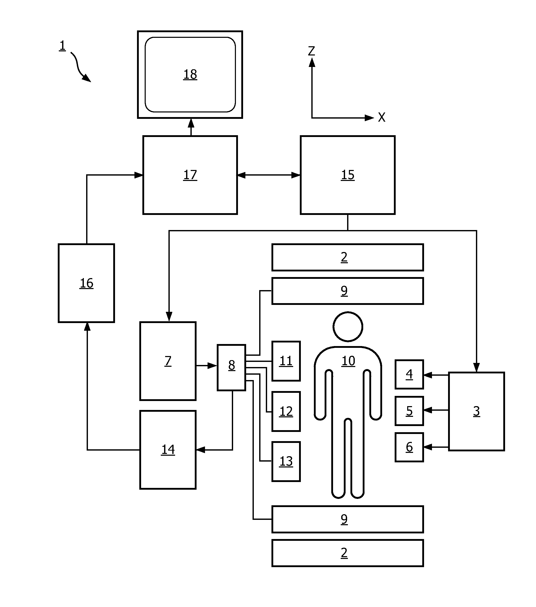
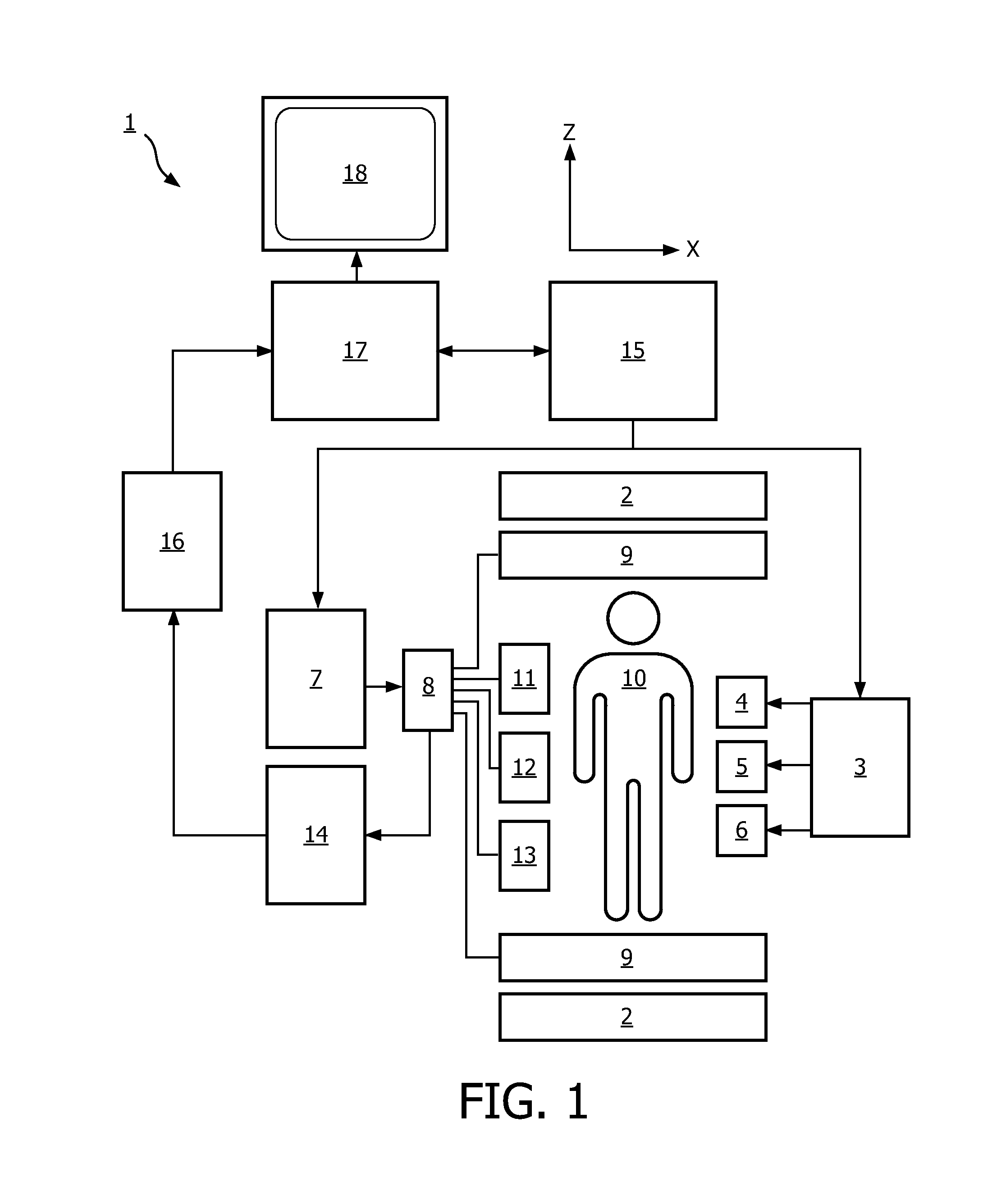
[0034]With reference to FIG. 1, an MR imaging system 1 is shown. The system comprises superconducting or resistive main magnet coils 2 such that a substantially uniform, temporarily constant main magnetic field B0 is created along a z-axis through an examination volume.

[0035]A magnetic resonance generation manipulation system applies a series of RF pulses and switched magnetic field gradients to invert or excite nuclear magnetic spins, induce magnetic resonance, refocus magnetic resonance, manipulate magnetic resonance, spatially or otherwise encode the magnetic resonance, saturate spins and the like to perform MR imaging.

[0036]More specifically, a gradient pulse amplifier 3 applies current pulses to selected ones of whole body gradient coils 4, 5 and 6 along x, y and z-axes of the examination volume. An RF transmitter 7 transmits RF pulses or pulse packets, via a send / receive switch 8 to an RF antenna 9 to transmit RF pulses into the examination volume. A typical MR imaging sequenc...


PUM

PropertyMeasurementUnit
dynamic contrast enhanced magnetic resonance imagingaaaaaaaaaa
magnetic resonance imagingaaaaaaaaaa
magnetic resonanceaaaaaaaaaa

Abstract

The present invention relates to a method of performing dynamic contrast enhanced magnetic resonance imaging of an object (10) with signal separation for water and fat, the method comprising acquiring magnetic resonance datasets in the k-space using Dixon acquisition in a chemical shift encoding space and dynamic time resolution in a dynamic time space, wherein the dataset acquisition is performed employing undersampling, wherein the method further comprises: applying a compressed sensing reconstruction technique in the k-space, the chemical shift encoding space and the dynamic time space, said compressed sensing reconstruction resulting in reconstructed datasets, —performing Dixon reconstruction on the reconstructed datasets and dynamic contrast analysis on the Dixon reconstructed datasets.

Description

FIELD OF THE INVENTION[0001]The invention relates to a method of performing dynamic contrast enhanced magnetic resonance imaging with compressed sensing reconstruction, as well as a computer product and a magnetic imaging apparatus for performing dynamic contrast enhanced magnetic resonance imaging of an object.BACKGROUND OF THE INVENTION[0002]Image-forming MR methods which utilize the interaction between magnetic field and nuclear spins in order to form two-dimensional or three-dimensional images are widely used nowadays, notably in the field of medical diagnostics, because for the imaging of soft tissue they are superior to other imaging methods in many respects and do not require ionizing radiation and they are usually not invasive.[0003]According to the MR method in general, the body of a patient or in general an object to be examined is arranged in a strong, uniform magnetic field B0 whose direction at the same time defines an axis, normally the z-axis, of the coordinate system...

Claims


Application Information

Patent Timeline
Patent Type & Authority Patents(United States)
IPC IPC(8): G06K9/40G01N24/08G01R33/48G01R33/56G01R33/561G01R33/563G06T5/00
CPCG06T5/007G01N24/08G01R33/4828G01R33/5611G01R33/56308G01R33/5635G01R33/5601G01R33/5607G01R33/5615G01R33/54G01R33/561
Inventor BOERNERT, PETERDONEVA, MARIYA
Owner KONINKLIJKE PHILIPS ELECTRONICS NV
Why Eureka
Try Eureka