Peakforce photothermal-based detection of IR nanoabsorption

a photothermal and nanoabsorption technology, applied in the field of making nanoidentification sample property measurements, can solve the problems of limited chemically specific information, difficult simultaneous spectroscopic implementations delivering chemical specificity and sensitivity on the molecular level, and limited optical diffraction, so as to achieve the effect of minimizing sample preparation and improving resolution

Inactive Publication Date: 2015-02-10
BRUKER NANO INC
View PDF80 Cites 11 Cited by
  • Summary
  • Abstract
  • Description
  • Claims
  • Application Information

AI Technical Summary

Benefits of technology

[0027]Using Peak Force Tapping® mode AFM, the preferred embodiments overcome the drawbacks with the prior art, including PTIR, by directing light overhead of the sample and locally exciting the photothermal response at the tip-sample interface. Resolution is improved and sample preparation is minimized.

Problems solved by technology

However, despite ongoing progress in the development of imaging techniques with spatial resolution beyond the diffraction limit, simultaneous spectroscopic implementations delivering chemical specificity and sensitivity on the molecular level have remained challenging.
Far-field localization techniques can achieve spatial resolution down to about 20 nm by point-spread function reconstruction but typically rely on fluorescence from discrete molecular or quantum dot emitters, with limited chemically specific information.
Conventional IR spectroscopy and microscopy, however, have resolution on the scale of many microns, limited by optical diffraction.
At this time, no widely available instrument provides routine IR spectra with resolution below the diffraction limit.
At a wavelength absorbed by the sample, the absorption will typically cause a local increase in temperature and a rapid thermal expansion of the sample.
Free Electron Lasers are large expensive facilities.
This has the effect of a quick shock to the cantilever arm, which, if the ability of the cantilever to respond to this shock is slower than the shock, will result in exciting a resonant oscillation in the cantilever arm.
Although the set-up as described is promising, there is no real possibility of commercializing the same.
First, the IR light source used, the Free Electron Laser, is a very large and expensive facility, as noted.
Moreover, alternative benchtop sources of IR radiation have been limited by one or more characteristics that have made them unsuitable for a widely available instrument.
As further noted in the '521 publication, the apparatus described in the literature suffers from other limitations beyond the expensive and stationary IR source.
In addition to being costly and easy to damage, this arrangement requires special sample preparation techniques to prepare a sample thin enough such that the IR light can penetrate the sample to reach the probe.
Further, the actual signals generated can be small, thus requiring averaging of the signal and limiting the bandwidth of the technique.
One additional problem, however, is leakage of heat from a region that actually is absorbing the excitation energy, to a region that is not.
When using PTIR, as the sample is heated (i.e., a region of interest exhibits absorbing characteristics), the heat may, and often does, leak toward surrounding regions of the sample.
Clearly, this can lead to compromised data and / or poor resolution.
Despite ongoing progress in the development of imaging techniques with spatial resolution beyond the diffraction limit, spectroscopic implementations delivering chemical specificity and sensitivity on the molecular level have remained challenging.
Again, far-field localization techniques can achieve spatial resolution down to about 20 nm by point-spread function reconstruction but typically rely on fluorescence from discrete molecular or quantum dot emitters, with limited chemically specific information.
However, aperture-limited and wavelength-dependent fiber throughput reduces sensitivity, generally making SNOM unsuitable for spectroscopic techniques that have low intrinsic signal levels.
In the standard implementation, however, the direct illumination of the tip apex results in a three-to-four orders of magnitude loss in excitation efficiency, related to the mode mismatch between the diffraction-limited far-field excitation focus and the desired tens of nanometers near-field localization, as determined by the tip apex radius.
The resulting loss of sensitivity, together with a far-field background signal, often limit contrast and may cause imaging artifacts, presenting challenges for the general implementation of a wider range of spectroscopic techniques in s-SNOM.

Method used


Image

  • Peakforce photothermal-based detection of IR nanoabsorption
  • Peakforce photothermal-based detection of IR nanoabsorption
  • Peakforce photothermal-based detection of IR nanoabsorption

Examples


Embodiment Construction

[0040]An improved apparatus and method of performing chemical identification of a sample includes combining monochromatic IR excitation at a selected frequency with Peak Force Tapping® (PFT) AFM configured for making mechanical property measurements. Purely mechanical detection of IR nanoabsorption by a sample is realized, thereby facilitating chemical nanoidentification of a region of the sample.

Nanoscale Chemical Identification

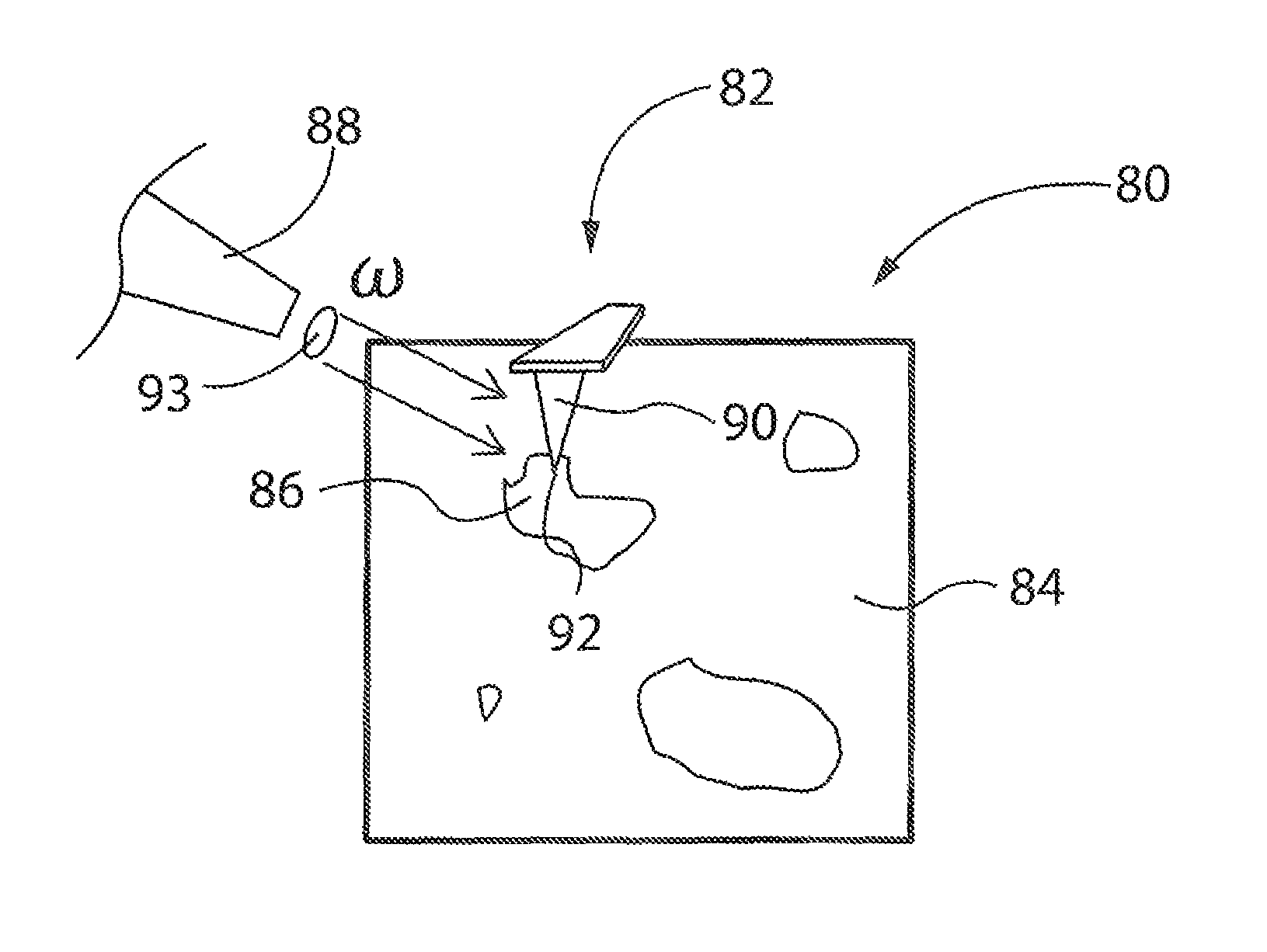
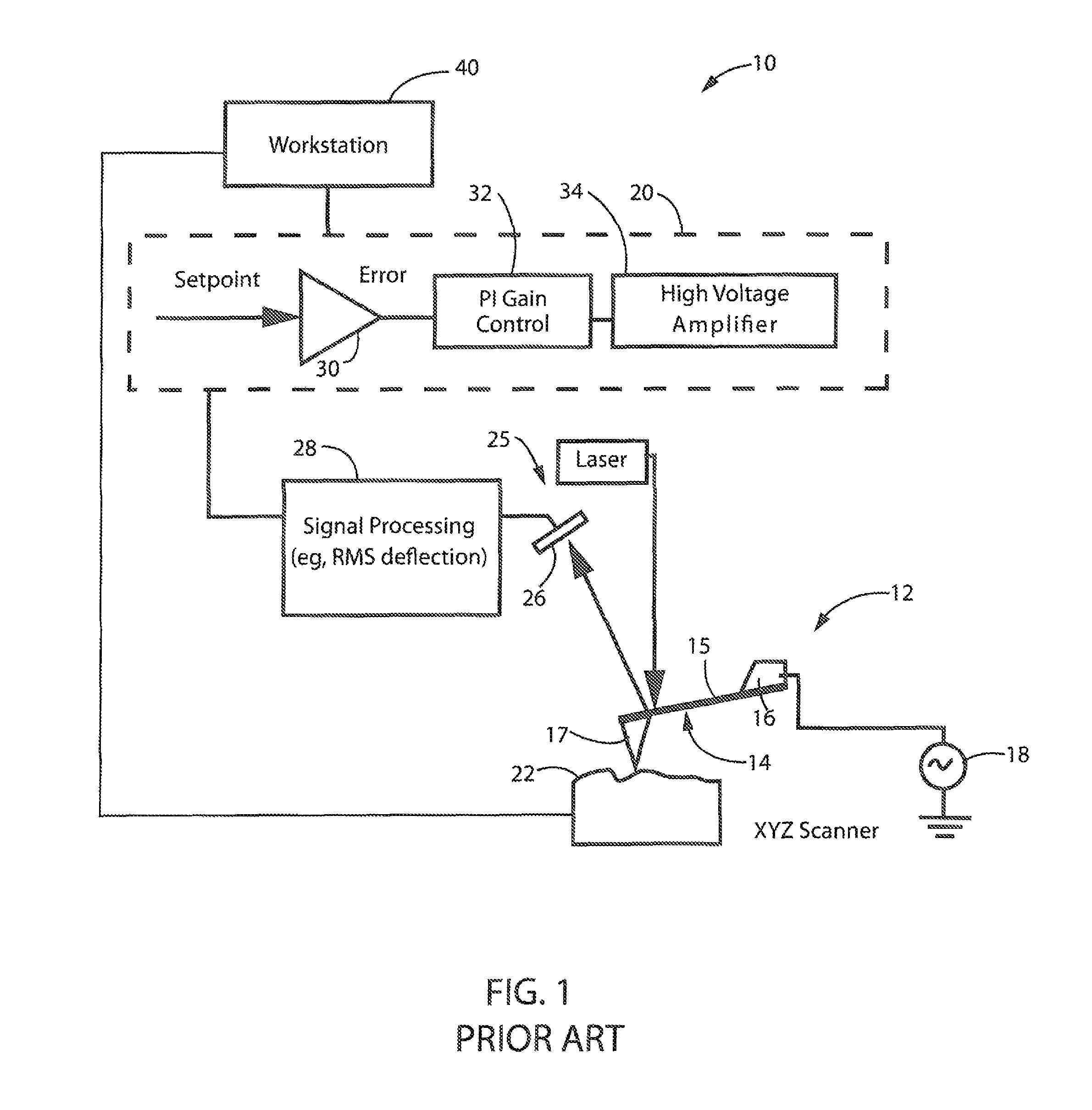
[0041]Turning initially to FIG. 2, a PeakForceIR apparatus 80 includes a PFT probe 82 that is introduced to a sample 84, and in particular, a region of interest 86. A source of IR electromagnetic radiation 88 directs light toward a tip 90 of probe 82, tip 90 including an apex of nanoscale dimensions 92 that primarily interacts with the surface of sample 84.

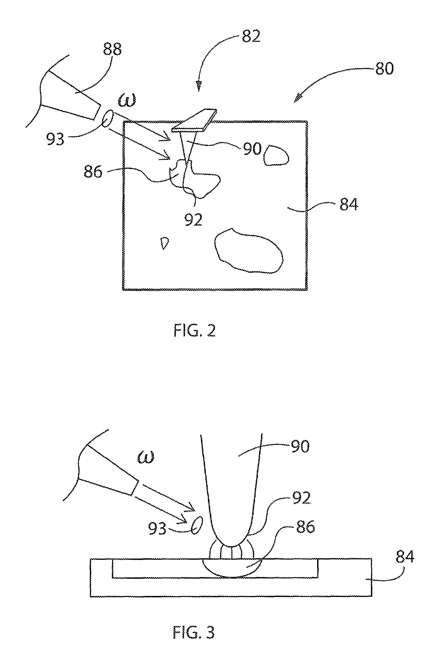
[0042]FIG. 3 illustrates more specifically the localized heating of the sample provided by the IR source. Source 88 directs IR light at a selected frequency, ω, toward sample 84 with an optical element (e....


PUM

PropertyMeasurementUnit
tip radiusaaaaaaaaaa
temperatureaaaaaaaaaa

Abstract

An apparatus and method of performing photothermal chemical nanoidentification of a sample includes positioning a tip of a probe at a region of interest of the sample, with the tip-sample separation being less than about 10 nm. Then, IR electromagnetic energy having a selected frequency, ω, is directed towards the tip. Using PFT mode AFM operation, absorption of the energy at the region of interest is identified. Calorimetry may also be performed with the photothermal PFT system.

Description

CROSS-REFERENCE TO RELATED APPLICATION[0001]The present application is a non-provisional application being converted from a provisional application U.S. Ser. No. 61 / 802,094, filed on Mar. 15, 2013, and titled Peak Force Photothermal-based Detection of IR Nanoabsorption, which itself is a continuation-in-part of U.S. Ser. No. 13 / 306,867, filed Nov. 29, 2011, which is a non-provisional of U.S. Ser. No. 61 / 417,837, filed Nov. 29, 2010, both entitled Method and Apparatus of Using Peak Force Tapping Mode to Measure Physical Properties of a Sample, which in turn is a continuation-in-part of U.S. Ser. No. 12 / 618,641, filed Nov. 13, 2009, which is a non-provisional of U.S. Ser. No. 61 / 114,399, filed Nov. 13, 2008, both entitled Method and Apparatus of Operating a Scanning Probe Microscope. The subject matter of these applications is hereby incorporated by reference in their entirety.BACKGROUND OF THE INVENTION[0002]1. Field of the Invention[0003]The preferred embodiments are directed to mak...

Claims


Application Information

Patent Timeline
Patent Type & Authority Patents(United States)
IPC IPC(8): G01Q60/24G01N21/35G01Q60/04G01Q30/20
CPCG01Q30/20G01N21/171G01N21/3563G01Q30/02G01Q60/32G01N2201/06113G01N2201/10G01N2201/12B82Y35/00
Inventor ANDREEV, GREGORY O.
Owner BRUKER NANO INC
Why Eureka
Try Eureka