Fluid machine provided with hermetic container that is subjected to pressure of working fluid

a technology of working fluid and fluid container, which is applied in the direction of liquid fuel engine components, arc welding apparatus, rotary piston liquid engines, etc., can solve the problems of increased production cost of hermetic container, compressor, and molten shell area cracks, etc., to reduce production cost, reduce stress, and suppress the formation of cracks in the weld area

Inactive Publication Date: 2015-02-24
SANDEN CORP
View PDF12 Cites 0 Cited by
  • Summary
  • Abstract
  • Description
  • Claims
  • Application Information

AI Technical Summary

Benefits of technology

[0018]In the fluid machine according to items 1 and 2, the hermetic container is constructed by joining two shells together by a single butt weld joint, or in other words, by forming a weld in a groove over the entire length of the groove by a single step of welding. Assembling the hermetic container by a single step leads to a reduced cost of producing the hermetic container, and thus, the compressor.
[0019]The provision of the space alleviates concentration of stress on the weld area, thereby suppressing formation of cracks in the weld area. It also prevents flying particles and sparks from coming into the hermetic container during welding. Further, it prevents the weld from extending into the hermetic container and at the same time allows the weld to form with a sufficient thickness, resulting in an increased weld strength, and thus, an increased reliability of the fluid machine.
[0020]In the fluid machine according to item 3, the shells are butted together with the slant faces of the sealing portions in contact with each other. This design allows assembly error in the direction in which the shells are butted together and in the direction at right angles to this direction, namely shells' radial direction. This obviates the need for strict shell-size accuracy control and provides ease of positioning and assembling the shells.
[0021]During welding, particles and sparks are likely to fly toward the radial center of the shells. The sealing portions with their slant faces in contact with each other can effectively prevent the particles and sparks from coming into the hermetic container during welding.
[0022]During welding, particles and sparks are likely to fly toward the radial center of the shells. In the fluid machine according to item 4, sealing portions are provided such that more than one face of one of the sealing portion is brought into contact with more than one face of the other sealing portion. The sealing portions thus provide a step-like sealing, leading to an increased reliability of preventing the particles and sparks from coming into the hermetic container during welding.
[0023]In the fluid machine according to item 5, the shells each have a root portion shaped to help an inner end portion of the weld to form at an acute angle to the surface of the recess. This allows the weld to be so formed as to connect to the recess surface smoothly at an obtuse angle, and thus, makes it unlikely that stress is concentrated at the boundary between the weld and the base material, or shells and produces cracks. The weld area has thus a further increased weld strength.

Problems solved by technology

The hermetic container disclosed in the aforementioned prior-art document is composed of three members, which means that it requires welding at two locations at least, and thus, more assembly steps, resulting in an increased cost of producing the hermetic container, and thus, the compressor.
When applied to a hermetic container composed of two cup-shaped shells, this method cannot effectively release heat generated in welding due to the absence of a central shell, resulting in unallowable thermal deformation of the shells, which leads to formation of cracks in the molten areas of the shells after welding.
Due to such cracks, the weld may not have a sufficient thickness, or the weld area may include non-welded parts.
If force or moment produces stress concentrated on such parts, the hermetic container may undergo fatigue breakdown.

Method used


Image

  • Fluid machine provided with hermetic container that is subjected to pressure of working fluid
  • Fluid machine provided with hermetic container that is subjected to pressure of working fluid
  • Fluid machine provided with hermetic container that is subjected to pressure of working fluid

Examples


Embodiment Construction

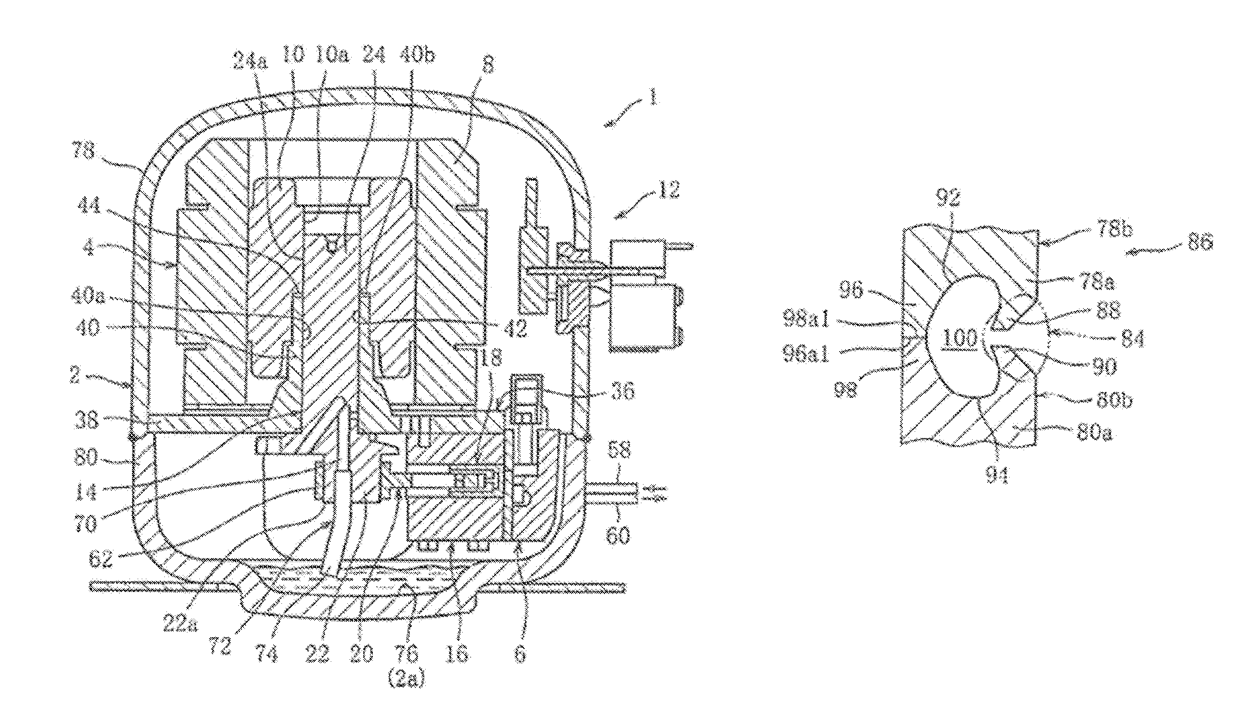
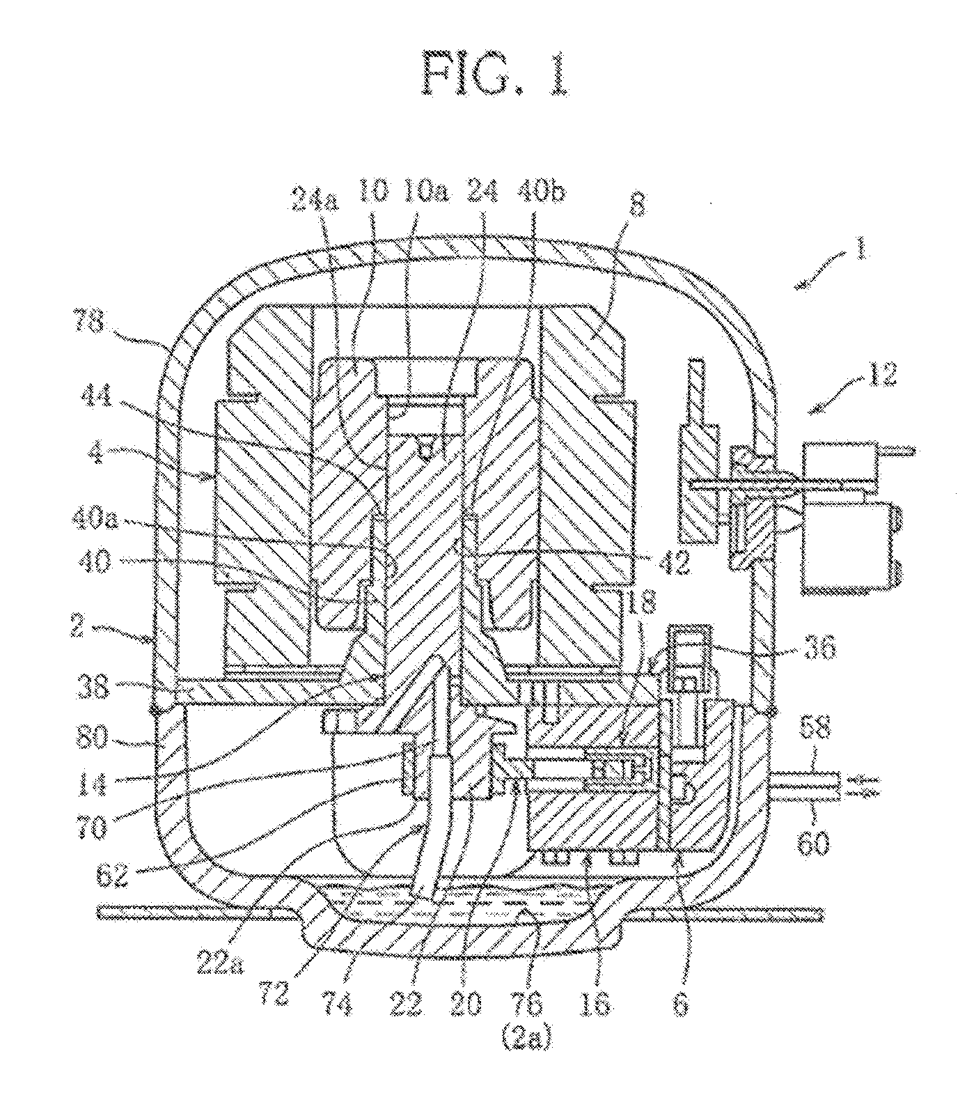
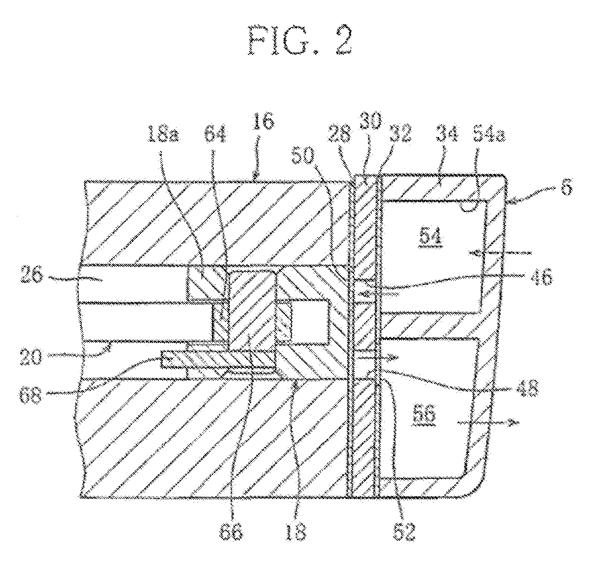
[0033]FIGS. 1 to 4 show a compressor 1 presented as a first embodiment of fluid machine.

[0034]The compressor 1 is a hermetic reciprocating compressor, which belongs to the class of positive-displacement compressors called reciprocating compressors or piston compressors and which is incorporated into, for example an automatic vending machine to constitute a refrigeration cycle circuit, not shown.

[0035]The refrigeration cycle circuit has a circulation path along which a refrigerant, or working fluid of the compressor 1 circulates. The refrigerant is for example carbon dioxide, which is a non-combustible natural refrigerant.

[0036]As seen in FIG. 1, the compressor 1 comprises a hermetic container 2 enclosing an electric motor (drive unit) 4 and a compressing mechanism (driven unit) 6, the latter being supplied with drive power from the former.

[0037]The electric motor 4 comprises a stator 8 supplied with current to generate a magnetic field, and a rotor 10 rotating in the magnetic field ...


PUM

PropertyMeasurementUnit
thicknessaaaaaaaaaa
thicknessaaaaaaaaaa
thicknessaaaaaaaaaa

Abstract

Provided is a fluid machine which can be produced to have an increased weld strength and an increased reliability, at a reduced production cost. A first and a second shells (78, 80), each having a rim and a sealing portion constituting part of the rim, are butted together with the rims (78a, 80a) held together to form a groove (82) and with the sealing portions (96, 98) in contact with each other, and joined together by a weld (84) formed in the groove over the entire length of the groove to be separated from the sealing portions by a space (100).

Description

RELATED APPLICATIONS[0001]This application is a U.S. National Phase Application under 35 USC 371 of International Application PCT / JP2011 / 000368 filed Jan. 24, 2011.[0002]This application claims the priority of Japanese application No. 2010-015414 filed Jan. 27, 2010, the entire content of which is hereby incorporated by reference.TECHNICAL FIELD[0003]This invention relates to a fluid machine, specifically a fluid machine suited to form a hermetic reciprocating compressor compressing carbon-dioxide refrigerant.BACKGROUND ART[0004]There is known a hermetic compressor which belongs to this class of fluid machine and which comprises an electric motor and a compressing mechanism arranged in a hermetic container such that drive power is transmitted from the electric motor to the compressing mechanism to compress a refrigerant.[0005]Patent document 1 discloses a hermetic container composed of three members: a center, a top and a bottom shells, the center shell being a tubular member open a...

Claims


Application Information

Patent Timeline
Patent Type & Authority Patents(United States)
IPC IPC(8): F04C15/00F04C27/00B23K9/028B23K9/16B23K9/173B23K33/00F01C19/00F04B39/12F04B39/14F04C23/00
CPCF04B39/121B23K9/0286B23K9/164B23K9/173B23K33/006F04B39/14B23K2201/12F01C19/005F04C23/008F04C2230/231F04C2240/30Y10S418/01B23K2101/12B23K9/00B23K33/00F04B39/12
Inventor KOBAYASHI, NORIYUKIITO, HITOMI
Owner SANDEN CORP
Why Eureka
Try Eureka