Connector having improved contacts

a technology of connecting contacts and contacts, applied in the direction of coupling contact members, coupling device connections, two-part coupling devices, etc., can solve the problems of electrical interference between adjacent signal conductors, increased possibility of electrical noise generation in the connector, and generally smaller electronic systems

Active Publication Date: 2015-02-24
AMPHENOL CORP
View PDF17 Cites 12 Cited by
  • Summary
  • Abstract
  • Description
  • Claims
  • Application Information

AI Technical Summary

Benefits of technology

[0013]It is an object of the invention to preserve the electrical characteristics of the signal path along the entire length of the conductors, and especially at the mating interface where the beam conductors couple with backplane blade conductors. It is another object of the invention to achieve desired electrical characteristics by coupling the edges of the beams and decoupling the over-travel regions of the blade portions. It is a further object of the invention to make the signal conductor narrow and the spacings between the signal conductor and the ground conductors narrower and, in the intermediate portion, to have the signal and ground conductors close to one another. It is a further object of the invention to provide a mating interface with narrowed blades so that the sides of the signal blades are further away from the sides of the neighboring ground blades, and especially in an over-travel region. And, it is another object of the invention to provide a mating interface with improved impedance matching and signal transmission by means of flexible conductor beams that are wider measured from outer edge to outer edge and that connect to the narrowed blades. It is still another object of the invention to minimize the currents and charges in the over-travel region of the mating interface between the conductors and the blades. It is yet another object of the invention to provide a mating conductor with sufficient flexibility, yet is strong enough to provide a sufficient normal force to maintain a reliable connection with a blade. It is another object of the invention to provide an alternate design of a single point-of-contact beam which has the effective mechanical width and stiffness adjustable independently of the effective electrical width as determined by the distance between its extreme outer edges. It is another object of the invention to move the outer edge of the conductor outward to maintain the coupling between signal and ground conductors. It is another object of the invention to widen the outer edges of the beams and have the beams selectively spaced apart from the grounds and the other half of the differential pair independent of the blades. It is yet another object of the invention to reduce the effect of the stub by making the blades narrower.
[0015]Accordingly, the distance between the outer edges of the contact beams is wider than the outer edges of a blade which they mate with. This causes the coupling between the outer edges of the beam portions of various conductors to be stronger than the coupling between the corresponding edges of the blades in the over-travel region.

Problems solved by technology

Electronic systems have generally become smaller, faster and functionally more complex.
One of the difficulties in making a high density, high speed connector is that electrical conductors in the connector can be so close that there can be electrical interference between adjacent signal conductors.
As signal frequencies increase, there is a greater possibility of electrical noise being generated in the connector in forms such as reflections, crosstalk and electromagnetic radiation.
However, it can be challenging to obtain a mating interface which has a desired impedance because in the area where mating conductors 10, 12 overlap, the effective thickness of the conductors can be too great and the spacing between different conductors too narrow.
This results in a deleterious effect on the electrical characteristics of the mating interface due to the stronger coupling between the stub portions of the blades.
This, in turn, results in diminished signal transmission, increased signal reflection and crosstalk at the mating interface and results in diminished impedance matching.

Method used


Image

  • Connector having improved contacts
  • Connector having improved contacts
  • Connector having improved contacts

Examples


Embodiment Construction

[0020]In describing a preferred embodiment of the invention illustrated in the drawings, specific terminology will be resorted to for the sake of clarity. However, the invention is not intended to be limited to the specific terms so selected, and it is to be understood that each specific term includes all technical equivalents that operate in similar manner to accomplish a similar purpose.

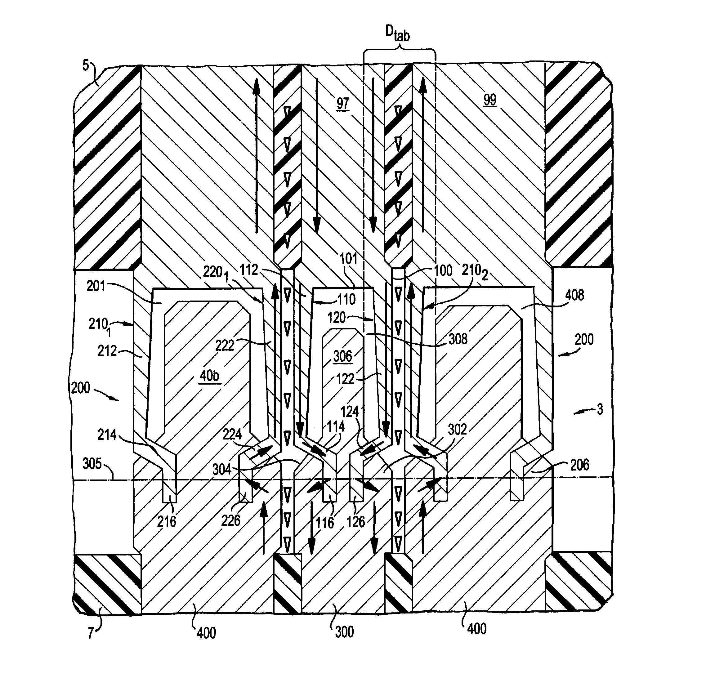
[0021]Turning to the drawings, FIG. 2(a) shows the mating interface 3 of an interconnection system. The separable mating interface 3 has a coplanar waveguide structure with improved electrical performance. The mating interface 3 generally includes the mating contacts or conductors 100, 200 of the daughter card connector which are coupled with the conductors or blades 300, 400 of the backplane connector. The conductors 100, 200 include signal contacts 100 and ground contacts 200 which are at a distal end section of respective intermediate portions 97, 99. The intermediate portions 97, 99 are embedde...


PUM


Abstract

An electrical connector for connecting a conductor of a daughter card connector wafer with a blade in the housing of a backplane connector. The daughter card conductor has a body with two elongated beams extending outward from the body. The two elongated beams each have an outer edge and an inner edge, whereby an opening is defined between the inner edges. The backplane conductor has a body with a narrowed tab portion extending outward from said second conductor body. The narrowed tab portion having outer opposite edges and is sized so that the narrowed tab portion fits between at least a portion of the outer edges of the two elongated beams, and in some cases between at least a portion of the inner edges of the two elongated beams.

Description

RELATED APPLICATIONS[0001]This application claims the benefit of U.S. Provisional Application No. 61 / 440,225, filed Feb. 7, 2011, the entire contents of which are incorporated herein by reference.BACKGROUND OF THE INVENTION[0002]1. Field of the Invention[0003]The present invention relates to electrical interconnection systems and more specifically to improved signal integrity in interconnection systems, particularly in high speed electrical connectors.[0004]2. Background of the Related Art[0005]Electrical connectors are used in many electronic systems. It is generally easier and more cost effective to manufacture a system on several printed circuit boards (“PCBs”) that are connected to one another by electrical connectors than to manufacture a system as a single assembly. A traditional arrangement for interconnecting several PCBs is to have one PCB serve as a backplane. Other PCBs, which are called daughter boards or daughter cards, are then connected to the backplane by electrical ...

Claims


Application Information

Patent Timeline
Patent Type & Authority Patents(United States)
IPC IPC(8): H01R13/648H01R13/26H01R24/62
CPCH01R13/26H01R24/62
Inventor GAILUS, MARK W.KIRK, BRIAN P.COHEN, THOMAS S.
Owner AMPHENOL CORP
Why Eureka
Try Eureka