
Top plate of microwave plasma processing apparatus, plasma processing apparatus and plasma processing method

a plasma processing apparatus and microwave technology, applied in plasma technology, electrogenerative processes, coatings, etc., can solve the problems of non-uniform distribution of plasma, inability to uniformly generate plasma, and serious phenomenon at a low microwave power, so as to achieve uniform and stable plasma

Active Publication Date: 2015-03-03
TOKYO ELECTRON LTD
View PDF18 Cites 10 Cited by
  • Summary
  • Abstract
  • Description
  • Claims
  • Application Information

AI Technical Summary

Benefits of technology

The invention is a plasma processing apparatus with a microwave plasma generator. The apparatus has a recess on the top plate, which allows for resonance absorption of the microwave and creates a uniform and stable plasma. Additionally, the apparatus can generate plasma even if the atmosphere in the chamber changes, without needing to change the top plate or microwave wavelength.

Problems solved by technology

If the top plate is simple and flat, the microwave is not uniformly propagated in a central portion and a peripheral portion of the top plate, and, thus, plasma cannot be uniformly generated.
As a result, there has been a problem in that plasma is non-uniformly distributed due to non-uniformity of propagation in a circumferential direction.
In particular, such a phenomenon becomes serious at a low microwave power.
Further, in order to control propagation in a diametric direction and propagation in a circumferential direction at the same time, a shape of the top plate becomes complicated, which causes an increase in manufacturing costs.

Method used


Image

  • Top plate of microwave plasma processing apparatus, plasma processing apparatus and plasma processing method
  • Top plate of microwave plasma processing apparatus, plasma processing apparatus and plasma processing method
  • Top plate of microwave plasma processing apparatus, plasma processing apparatus and plasma processing method

Examples


embodiment

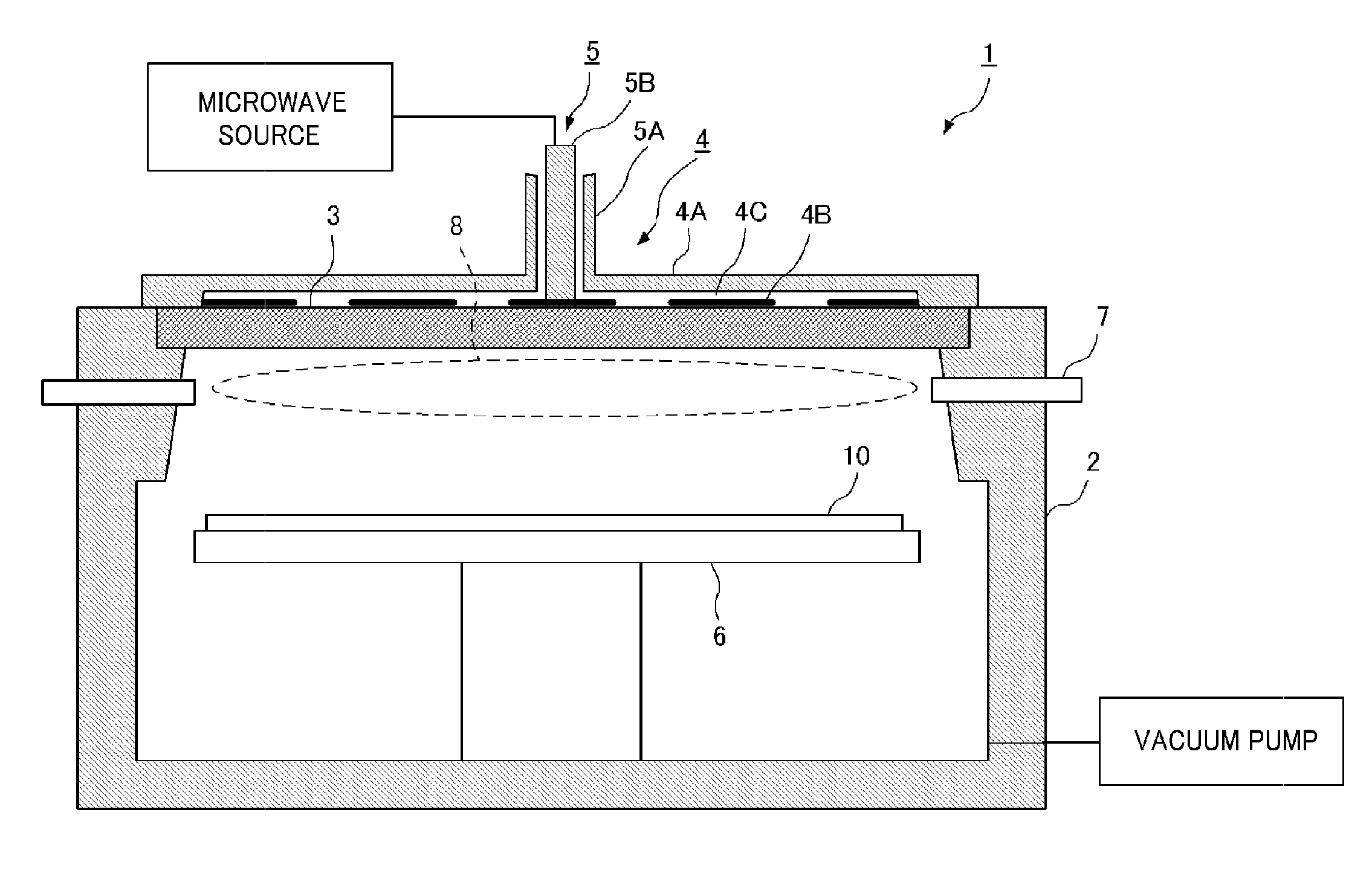
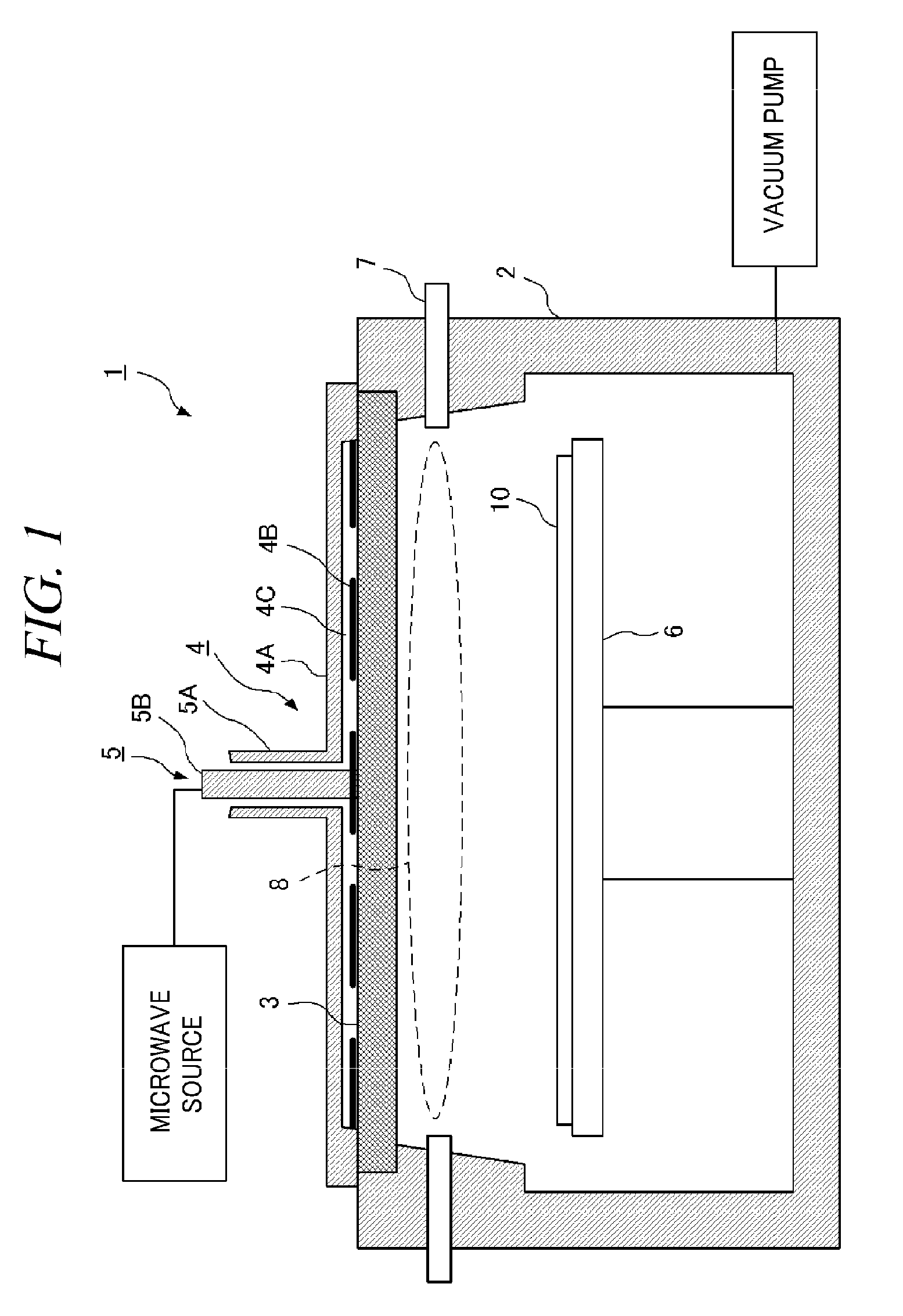
[0049]Hereinafter, a top plate of a microwave plasma processing apparatus in accordance with a first aspect of the present invention will be explained in detail with reference to the accompanying drawings. Further, same or like parts in the drawings will be assigned same reference numerals and explanation thereof will be omitted. FIG. 1 is a cross-sectional view of a plasma processing apparatus in accordance with an embodiment of the present invention. A plasma processing apparatus 1 includes a plasma generation chamber 2, a top plate (a dielectric member) 3, an antenna 4, a waveguide 5, a substrate holding table 6, and a gas passage 7. The antenna 4 includes a waveguide member (a shield member) 4A, a radial line slot antenna (RLSA) 4B, and a wavelength shortening plate (a dielectric member) 4C. The waveguide 5 is a coaxial waveguide including an outer waveguide 5A and an inner waveguide 5B.

[0050]The plasma generation chamber 2 of the plasma processing apparatus 1 is closed by the t...

experimental example 1

[0069]FIGS. 7A and 7B show examples for checking an effect of recesses 3A of a top plate 3 by a plasma experiment using the top plate 3 in accordance with the embodiment of the present invention. FIG. 7A shows an example (photo) of plasma in case of a flat top plate (hereinafter, referred to as “conventional top plate”), and FIG. 7B shows an example (photo) of plasma in case of a top plate having the recesses 3A of the present invention (hereinafter, referred to as “top plate of the present invention”).

[0070]A top plate 3 used in the experiment is made of quartz and the top plate of the present invention further includes a multiple number of recesses 3A as compared to the conventional top plate. A condition of plasma generation was common and the experiment was conducted by using an argon gas at a microwave power of about 2000 W and a pressure of about 1.33 Pa.

[0071]In case of the conventional flat top plate, plasma was generated non-uniformly and in particular, it is noticeable tha...

experimental example 2

[0072]FIGS. 8A and 8B show examples (photos) of generating plasma at different pressures by using the top plate 3 in accordance with the embodiment of the present invention. FIG. 8A shows a case (condition A) where a pressure is about 1.33 Pa, and FIG. 8B shows a case (condition B) where a pressure is about 66.65 Pa. Other conditions than the pressure are the same as those of Experimental example 1. The experiment was conducted at a pressure of about 1.33 Pa as a condition A and at a pressure of about 66.65 Pa as a condition B. There has been made a comparison on whether or not plasma is generated and on a plasma distribution if the plasma is generated.

[0073]As shown in FIG. 8B, even when the experiment was conducted at a relatively high pressure of the condition B, plasma could be generated in the same pattern. Further, as a result of a comparison between FIG. 8A and FIG. 8B, it can be seen from both drawings that plasma was generated within the multiple number of recesses. As a re...


PUM

PropertyMeasurementUnit
pressureaaaaaaaaaa
pressureaaaaaaaaaa
thicknessaaaaaaaaaa

Abstract

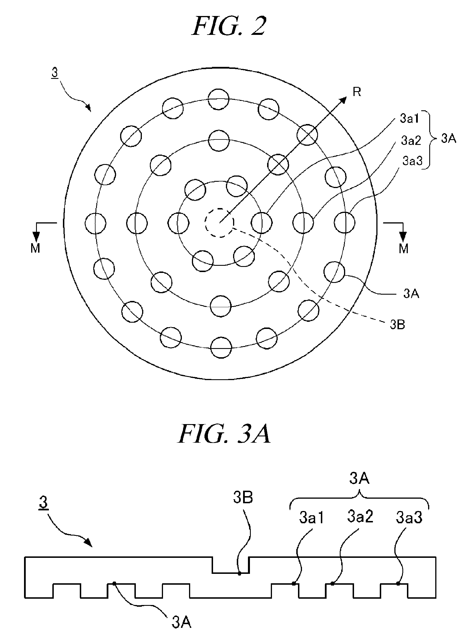
A plasma generation chamber of a plasma processing apparatus is closed by a top plate 3. The top plate 3 has recesses 3A on its surface facing the plasma generation chamber and a central recess 3B on an opposite surface. The top plate 3 is coupled to an antenna thereon. If a microwave is supplied to the antenna, the microwave is radiated through slots of the antenna. The microwave is propagated through the top plate 3 such that the microwave has a plane of polarization and the microwave forms a circularly polarized wave as a whole. Here, resonance absorption of the microwave occurs at a side surface of recesses 3A and the microwave is propagated within the recesses 3A in a single mode. Strong plasma can be generated within each of the recesses 3A, so that a stable plasma mode can be generated in the top plate 3.

Description

TECHNICAL FIELD[0001]The present invention relates to a top plate of a microwave plasma processing apparatus, a plasma processing apparatus, and a plasma processing method.BACKGROUND ART[0002]A plasma processing technology has been widely used for many semiconductor devices such as an integrated circuit, a liquid crystal display and a solar cell. Although the plasma processing technology has been used for thin film deposition process or an etching process in a semiconductor manufacturing process, a highly advanced plasma process is required for a product having a higher performance and multi function (for example, an ultra fine process technology). In particular, a microwave plasma processing apparatus capable of generating plasma of low pressure and high density has drawn attention.[0003]A plasma processing apparatus using a RLSA (Radial Line Slot Antenna) plasma microwave source ionizes a gas by microwave discharge and generates plasma. A microwave is supplied through slots of the...

Claims


Application Information

Patent Timeline
Patent Type & Authority Patents(United States)
IPC IPC(8): C23C16/00H01L21/306C23F1/00H01J37/32H05H1/46
CPCH05H1/46H01J37/32192H01J37/32211H01J37/3222H01J37/32238
Inventor TIAN, CAIZHONGISHIBASHI, KIYOTAKANOZAWA, TOSHIHISA
Owner TOKYO ELECTRON LTD
Learn More