Plasma generating electrode and plasma reactor

a technology of plasma generating electrodes and plasma reactors, which is applied in the direction of machines/engines, mechanical equipment, separation processes, etc., can solve the problems of unit electrodes, poor productivity, and increased parts number, and achieve uniform and stable plasma, excellent heat resistance, and reduced distortion

Inactive Publication Date: 2006-07-13
NGK INSULATORS LTD +1
View PDF3 Cites 12 Cited by
  • Summary
  • Abstract
  • Description
  • Claims
  • Application Information

AI Technical Summary

Benefits of technology

[0017] Thus, according to the plasma generating electrode of the present invention, since each of a pair of unit electrodes (upper unit electrode and lower unit electrode) includes a plate-like ceramic body as a dielectric and a conductive film disposed inside the ceramic body, the plasma generating electrode can generate uniform and stable plasma. Moreover, since the basic units 1, each of which is formed by a pair of unit electrodes, are hierarchically layered to form the electrode unit, which is used as a plasma generating electrode, distortion can be reduced even if thermal stress occurs, so that a plasma generating electrode exhibiting with excellent heat resistance is obtained. Moreover, since the protrusions are arranged between the unit electrodes in a predetermined pattern, looseness deflection of the electorode plate or the like is reduced because the unit electrodes are supported by the protrusions. This allows the unit electrodes to maintain their planar shape, so that the distance between the unit electrodes is entirely constant (over the entire surface), whereby plasma becomes uniform. Moreover, since the protrusions are arranged between the unit electrodes, creeping discharge generated in the area where the protrusion is in contact with the unit electrode (corner of protrusion) extends through the space formed between the protrusions. Therefore, the creeping discharge can be transformed into uniform barrier discharge between the unit electrodes at low energy injection. Since the plasma generating electrode of the present embodiment can be produced by layering the basic units produced in advance, assembly of parts does not become complex so that the productivity can be improved.
[0018] Since the plasma reactor of the present invention includes such a plasma generating electrode, the plasma reactor exhibits excellent productivity, can generate uniform and stable plasma, and exhibits excellent heat resistance.

Problems solved by technology

Therefore, the number of parts is increased and assembly becomes complex, thereby resulting in poor productivity.
However, since the unit electrode reduced in thickness tends to be deformed, the distance between the unit electrodes changes locally due to looseness of the unit electrode and is not uniform as a whole, so that plasma becomes nonuniform.
Moreover, the plasma generating electrode may break due to thermal stress when thermal stress is applied to the plasma generating electrode.

Method used


Image

  • Plasma generating electrode and plasma reactor
  • Plasma generating electrode and plasma reactor
  • Plasma generating electrode and plasma reactor

Examples


example 1

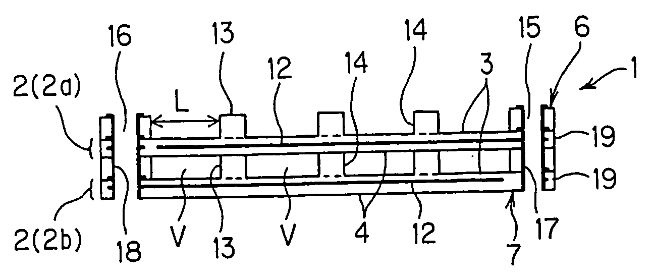
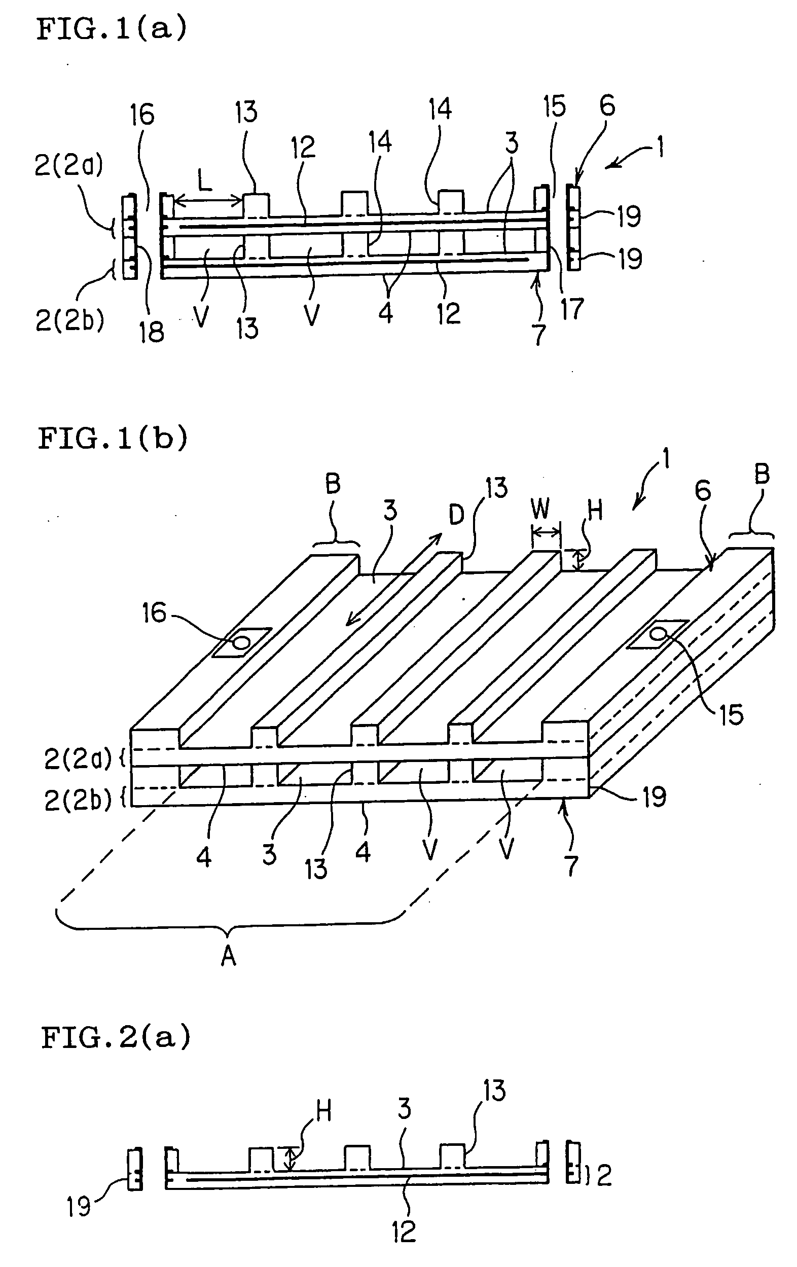
[0094] A unit in which the unit electrodes 2 (alumina dielectric electrodes) shown in FIG. 3 were layered in six stages (six-stage electrode unit) was produced. The size of the electrode in one stage was 50×100×1 mm, and the internal conductive film (electrode) was printed with a tungsten paste in the area of 40×80 mm to have a thickness of 10 μm. Conductive film through-holes having a diameter of 3 mm and an interval of 5 mm were regularly arranged in the conductive film so that the center of each through-hole was positioned at a vertex of an equilateral triangle. Protrusions having a width of 2 mm and a height of 1 mm were provided at intervals of 18 mm. A protrusion having a width of 8 mm and a height of 1 mm was provided on each end of the electrode, and a conduction through-hole having a diameter of 3 mm was formed at the center. A conductive film was formed in the conduction through-hole by using a tungsten paste and nickel plating on the tungsten paste.

[0095] Ten six-stage e...

example 2

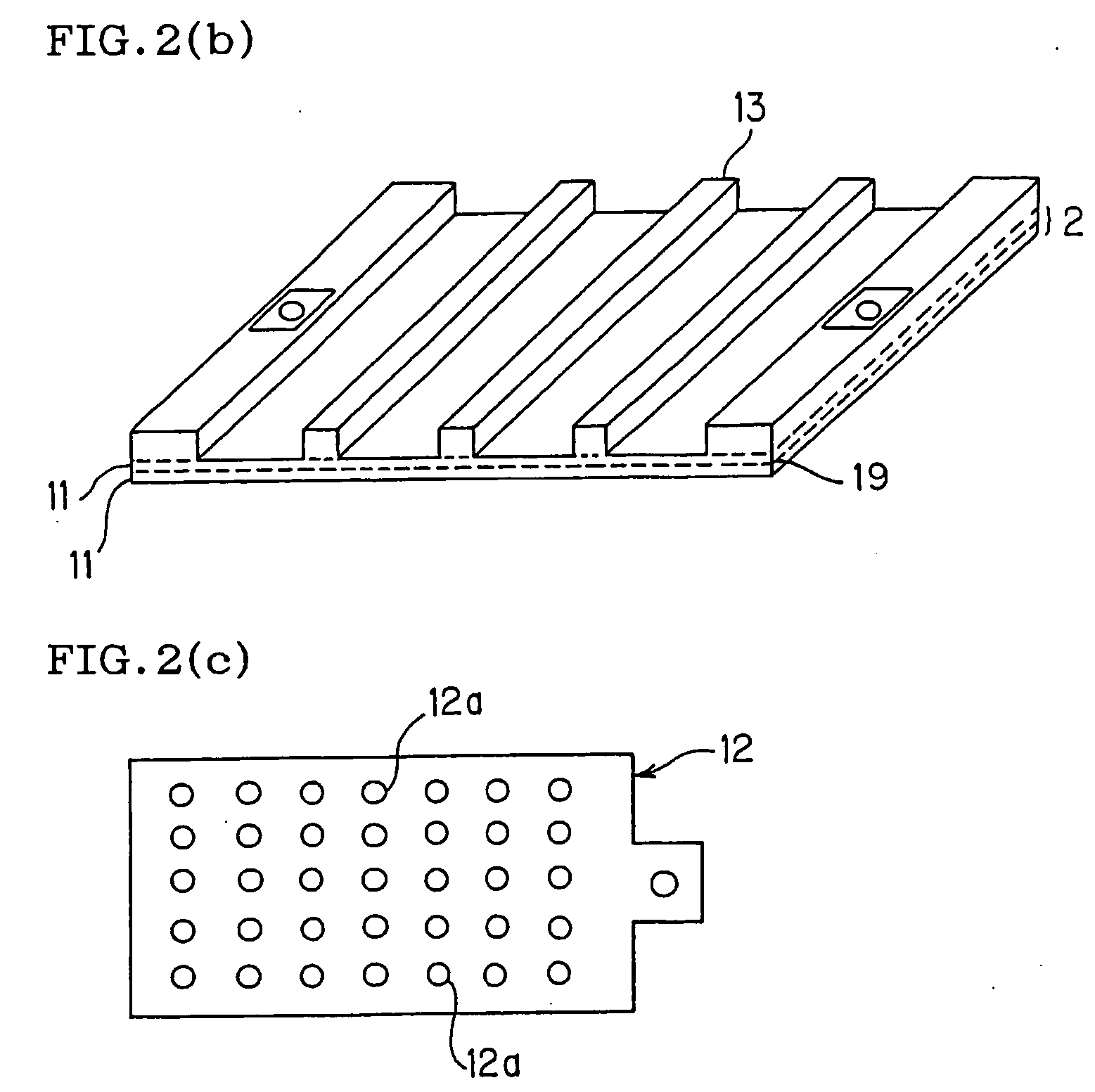
[0102] A sheet having regular protrusions shown in FIG. 8 was produced by extrusion. The flat portion was formed so that the thickness after firing was 0.25 mm. The protrusions regularly arranged on the flat portion were formed so that height after firing was 0.75 mm, the width after firing was 0.5 mm, and the intervals after firing was 5 mm. The protrusions on each end were formed so that the width after firing was 5 mm. The extruded sheet was produced so that the total width after firing was 70 mm. As the raw material, 93% purity alumina was used. After the addition of 5% of methyl cellulose (extrusion agent), a surfactant, and water, the components were kneaded and extruded. The extruded sheet was cut in the longitudinal direction of the protrusion so that the width after firing was 60 mm, and prefired at 1100° C. in the ambient air to obtain a protrusion-disposed ceramic body having a shape shown in FIG. 8.

[0103] A plate-like ceramic body shown in FIG. 9 was obtained by using t...


PUM

PropertyMeasurementUnit
Thicknessaaaaaaaaaa
Thicknessaaaaaaaaaa
diameteraaaaaaaaaa

Abstract

A plasma generating electrode of the present invention includes a pair of unit electrodes 2, each of the pair of unit electrodes 2 including a plate-like ceramic body 19 and a conductive film 12 disposed inside the ceramic body 19 and including a plurality of protrusions 13 on a front surface, the pair of unit electrodes 2 constituting a basic unit 1 by being hierarchically layered at intervals corresponding to thickness of the protrusion 13 in a state that a plurality of spaces which are open on each end in the arrangement direction of the protrusion are formed, the basic units 1 constituting an electrode unit in which the basic units 1 are hierarchically layered at intervals corresponding to the thickness of the protrusion 13, and the plasma generating electrode being capable of generating plasma in the three-dimensionally arranged spaces V upon application of voltage between the unit electrodes 2 constituting the electrode unit. Therefore, the plasma generating electrode is capable of generating uniform and stable plasma and exhibiting excellent heat resistance.

Description

TECHNICAL FIELD [0001] The present invention relates to a plasma generating electrode and a plasma reactor. More particularly, the present invention relates to a plasma generating electrode and a plasma reactor capable of generating uniform and stable plasma and exhibiting excellent heat resistance. BACKGROUND ART [0002] It is known that silent discharge occurs upon disposing a dielectric between two electrodes and applying a high alternating current voltage or a periodic pulsed voltage between the electrodes. In the resulting plasma field, active species, radicals, and ions are produced to promote a reaction and decomposition of gas. This phenomenon may be utilized to remove toxic components contained in engine exhaust gas or various kinds of incinerator exhaust gas. [0003] For example, a plasma reactor which treats NOx, carbon particulate, HC, and CO contained in engine exhaust gas or incinerator exhaust gas by passing the engine exhaust gas or various kinds of incinerator exhaust...

Claims


Application Information

Patent Timeline
Patent Type & Authority Applications(United States)
IPC IPC(8): B01J19/08B01D53/32F01N3/08H05H1/24
CPCB01D53/32B01D2259/818B01J19/088B01J2219/0809B01J2219/0835H05H1/24B01J2219/0894B01J2219/2453B01J2219/2487F01N3/0892B01J2219/0875H05H1/2437H05H1/2418H05H1/2441
Inventor MIYAIRI, YUKIOFUJIOKA, YASUMASAMASUDA, MASAAKISAKUMA, TAKESHIHATANO, TATSUHIKOSATO, YOSHIHIROSUZUKI, JUNICHI
Owner NGK INSULATORS LTD
Why Eureka
Try Eureka