Eureka AIR delivers breakthrough ideas for toughest innovation challenges, trusted by R&D personnel around the world.

Plasma reaction vessel, and method of producing the same

a reaction vessel and plasma technology, applied in the field of plasma reactors, can solve the problems of adversely affecting the performance of the plasma reactor, increasing the number of parts, and complex assembly, and achieve the effects of uniform and stable plasma, low power consumption, and reduced gas passage resistan

Inactive Publication Date: 2009-08-06
NGK INSULATORS LTD +1
View PDF6 Cites 2 Cited by
  • Summary
  • Abstract
  • Description
  • Claims
  • Application Information

AI Technical Summary

Benefits of technology

[0006]The invention has been achieved in view of the above-described problems, and provides a plasma reactor which can generate uniform and stable plasma at low power consumption and can reduce the passage resistance of a gas which passes through the plasma reactor, and a method of manufacturing the same.
[0035]The plasma reactor according to the invention can thus generate uniform and stable plasma at low power consumption and reduce the passage resistance of the gas which passes through the plasma reactor.

Problems solved by technology

However, since the distance between the electrodes must be reduced in order to form a structure which uniformly and stably generates plasma at low power consumption and allows a gas such as exhaust gas to efficiently pass through the plasma field, the number of parts is increased and assembly becomes complicated.
Moreover, a variation of the dimensions of each part which makes up the electrode used to generate plasma adversely affects the performance of the plasma reactor.
Furthermore, engine trouble or an increase in fuel consumption occurs due to an increase in the passage resistance of the gas which passes through the plasma reactor.

Method used


Image

  • Plasma reaction vessel, and method of producing the same
  • Plasma reaction vessel, and method of producing the same
  • Plasma reaction vessel, and method of producing the same

Examples


examples 1 to 6

[0215]Toluene as an organic solvent, a cellulose resin as a binder, and dioctyl phthalate (DOP) as a plasticizer were mixed with alumina powder. The mixture was sufficiently diffused and mixed using a trommel, and subjected to viscosity adjustment by a stirring bubble removal method under reduced pressure to prepare a slurry. A ceramic formed body having a thickness of 0.5 to 1 mm was tape-formed using the slurry by a doctor blade method. A tungsten cermet powder paste was printed on one side of the tape-shaped ceramic formed body, and then dried to form a conductor electrode. Another ceramic formed body was layered on the side on which the conductor electrode was formed to obtain a multilayer structure having a ceramic formed body / conductor electrode / ceramic formed body sandwich structure. The resulting multilayer structure was placed on a flat stand, and a gear wheel on which recesses and protrusions were formed at the surface was pressed against and rotated on the surface of the ...

examples 7 to 10

[0218]A plasma reactor provided with a spiral plasma generating electrode manufactured using cordierite (Examples 7 and 8) and a plasma reactor provided with a spiral plasma generating electrode manufactured using alumina (Examples 9 and 10) were obtained in the same manner as in the method of manufacturing the plasma reactors of Examples 1 to 6. The thermal shock resistance of the plasma generating electrode (cordierite plasma generating electrode and alumina plasma generating electrode) used in the plasma reactor was measured. The thermal shock resistance was measured by heating the plasma generating electrode for 30 minutes in an electric furnace, removing the plasma generating electrode from the electric furnace after heating, allows the plasma generating electrode to cool, and investigating the presence or absence of cracks on the surface of the plasma generating electrode due to cooling, by microscope observation. The results are shown in Table 2.

TABLE 2Heatingtemperature(° C....


PUM

PropertyMeasurementUnit
porosityaaaaaaaaaa
thicknessaaaaaaaaaa
thicknessesaaaaaaaaaa

Abstract

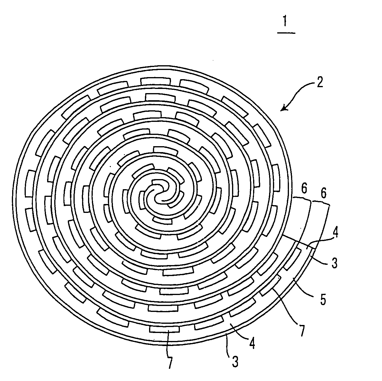
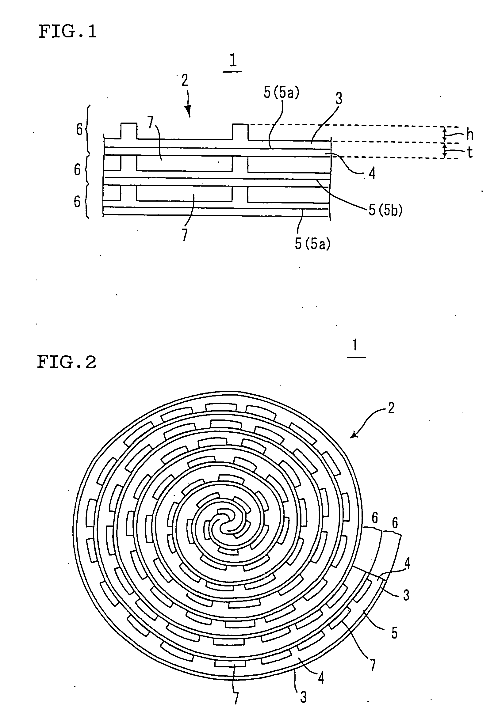
In the plasma reaction vessel (1) of the invention, two or more laminate-structures (6) having ceramic formed bodies (3, 4) in which a plasma generating electrode (2) capable of generating plasma is formed in two-tape-form, and an electrically continuous film-like electrically conductive electrode (5) held between the two ceramic formed bodies (3, 4) are formed in such a manner as to form a plasma generating space (7) containing mutual laminate planes therein. Of the electrically conductive electrodes (5), adjacent ones are capable of having electric discharge produced therebetween so as to generate the plasma in the plasma generating space (7) and of generating uniform stabilized plasma at low electric power, it being possible to reduce a passage resistance to a gas passing therein.

Description

[0001]This is a Division of application Ser. No. 10 / 544,527 filed Aug. 4, 2005, which in turn is a National Stage of PCT / JP04 / 001452 filed Feb. 12, 2004, which claims the benefit of Japanese Patent Application No. 2003-034425 filed Feb. 12, 2003. The disclosure of the prior applications is hereby incorporated by reference herein in its entirety.TECHNICAL FIELD[0002]The present invention relates to a plasma reactor and a method of manufacturing the same. More particularly, the invention relates to a plasma reactor which can generate uniform and stable plasma at low power consumption and can reduce the passage resistance of a gas which passes through the plasma reactor, and a method of manufacturing the same.BACKGROUND ART[0003]It is known that silent discharge occurs when applying a high-voltage alternating current or a periodic pulse voltage to a dielectric disposed between two electrodes, and active species, radicals, and ions are produced in the resulting plasma field to promote a...

Claims


Application Information

Patent Timeline
Patent Type & Authority Applications(United States)
IPC IPC(8): B01J19/08B01D53/92F01N3/08F01N3/28
CPCB01D53/92F01N3/0892Y10T29/49345F01N3/2828F01N2240/28F01N3/2825F01N3/01F01N3/08
Inventor IMANISHI, YUICHIROMIWA, SHINICHIABE, FUMIOMIYAIRI, YUKIO
Owner NGK INSULATORS LTD
Why Eureka
Eureka Blog
Learn More