Glass substrate-holding tool and method for producing an EUV mask blank by employing the same

a technology of holding tool and glass substrate, which is applied in the direction of manufacturing tools, originals for photomechanical treatment, instruments, etc., can solve the problems of scratching of the limit of the conventional photolithography method, and the accumulation of foreign substances on the central portion of the rear surface of the glass substra

Inactive Publication Date: 2015-03-03
ASAHI GLASS CO LTD
View PDF20 Cites 379 Cited by
  • Summary
  • Abstract
  • Description
  • Claims
  • Application Information

AI Technical Summary

Benefits of technology

[0023]In order to solve the above-mentioned problems of the prior art, it is an object of the present invention to provide a glass substrate-holding tool which is capable of preventing a glass substrate from being displaced or coming off and controlling the occurrence of scratches or the deposition of foreign substances on the glass substrate caused by holding action during the production of an EUV mask blank, and a method for producing EUV mask blank and a functional film-provided substrate for EUV mask blank by employing the glass substrate-holding tool.SUMMARY OF INVENTION
[0042]In accordance with the present invention, it is possible to prevent a substrate from being displaced or coming off and to control the occurrence of scratches or the deposition of foreign substances on the glass substrate caused by holding action during the production of EUV mask blank.
[0043]In the present invention, it is possible to carry out positioning so as to place the positional relationship between the glass substrate-holding tool and a glass substrate in a proper state by employing the glass substrate-holding tool including the glass substrate positioning devices.

Problems solved by technology

However, the conventional photolithography method has reached near to the limit while semiconductor devices have had finer patterns at an accelerated pace.
However, when a glass substrate is held by bringing a central portion of the rear surface of the glass substrate into contact with the catching and holding surface of an electrostatic chuck, it is likely that foreign substances deposit on the central portion of the rear surface of the glass substrate, or that the central portion of the rear surface of the glass substrate is scratched.
From this point of view, the deposition of foreign substrates or the occurrence of scratches on the central portion of the rear surface could cause a serious problem.
Accordingly, when an attempt is made to provide a catching and holding force enough to hold the glass substrate, the pressure per unit area applied to the caught and held portion is increased, which is likely to cause a problem of occurrence of scratches on the caught and held portion or of occurrence of foreign substances caused by such scratches.
Further, a large amount of charged foreign substances are likely to be attracted by an electrostatic field generated at the caught and held portion.
Since the caught and held portion is present on the outer edge portion of the rear surface, the effect caused by the occurrence of scratches or foreign substances is minor than a case where a similar problem is caused on the quality-guaranteed region of the rear surface.
On the other hand, when an attempt is made to reduce the catching and holding force of an electrostatic chuck in order to prevent the caught and held portion from being scratched or a large amount of foreign substances from being caught on the caught and held portion, the catching and holding force applied to a glass substrate become insufficient, which leads to a case where the glass substrate is likely to be displaced or come off during the production of EUV mask blank.
Accordingly, when such a tool is set to provide a holding force enough to hold the glass substrate, the pressure per unit area applied to the caught and held portion of the glass substrate is increased, which leads to a case where it is likely to cause a problem of occurrence of scratches on the caught and held portion or of occurrence of foreign substances caused by such scratches as in the electrostatic chuck.

Method used


Image

  • Glass substrate-holding tool and method for producing an EUV mask blank by employing the same
  • Glass substrate-holding tool and method for producing an EUV mask blank by employing the same
  • Glass substrate-holding tool and method for producing an EUV mask blank by employing the same

Examples


example 1

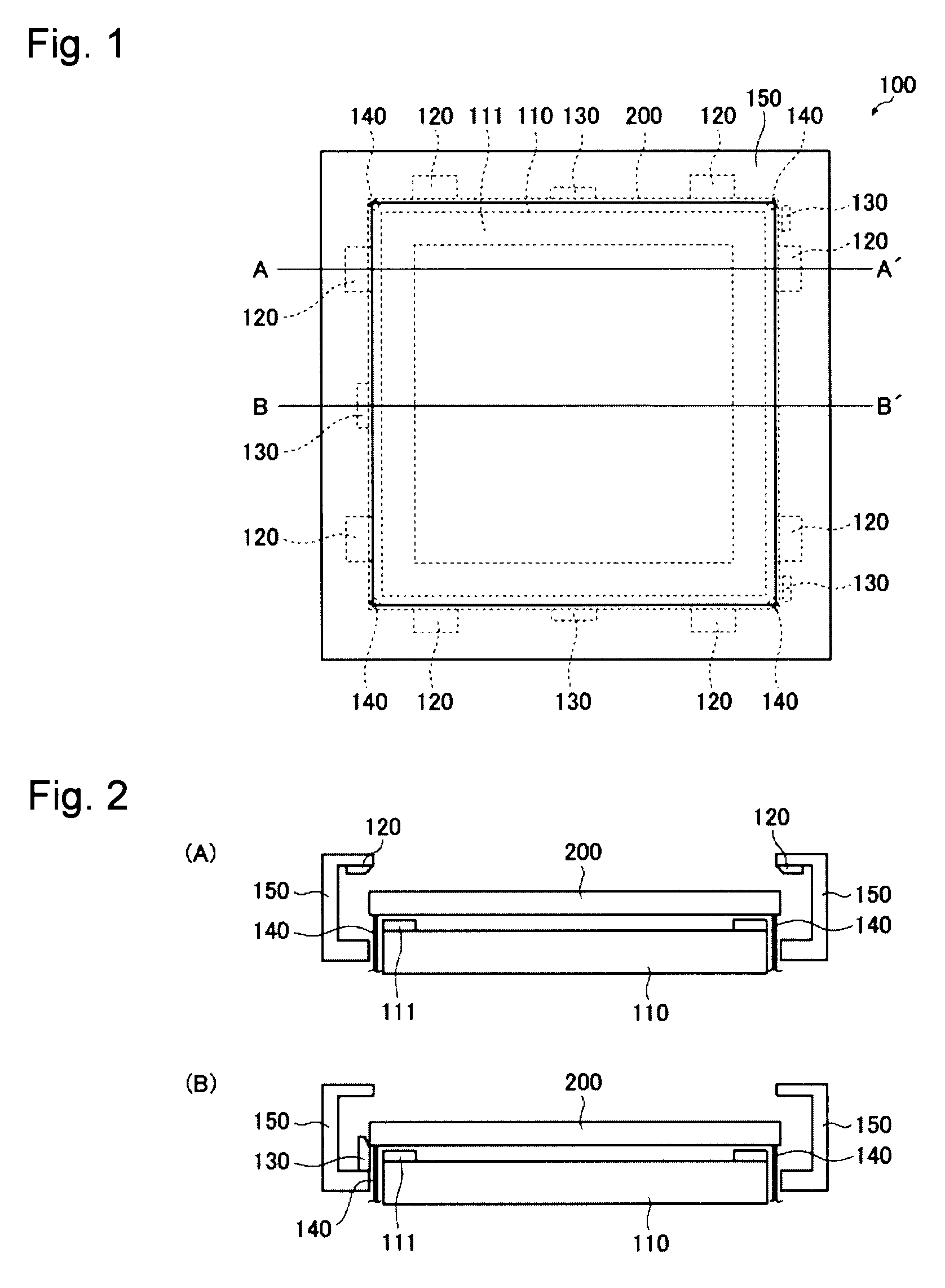
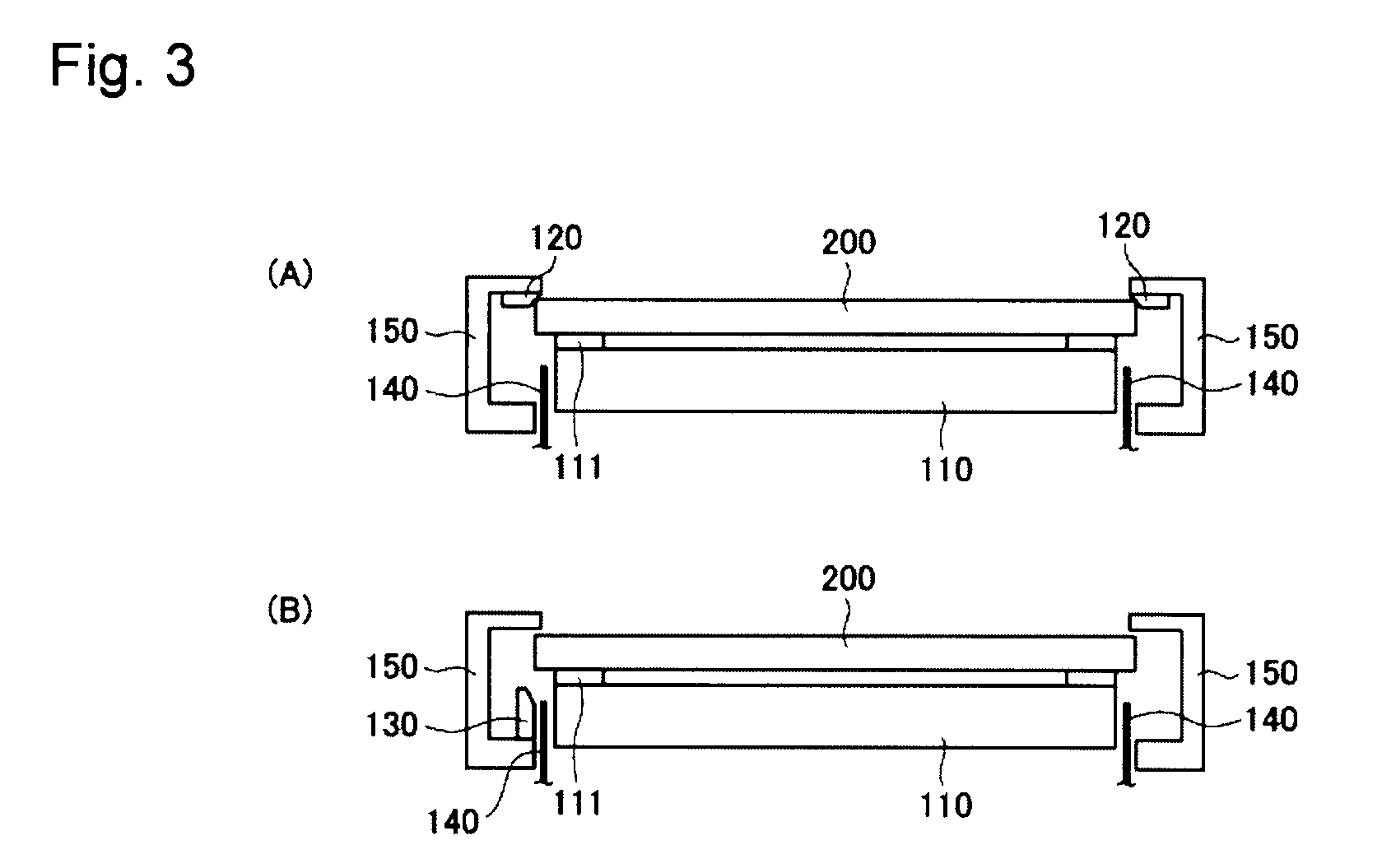
[0192]In Example 1, a glass substrate of 152.4 mm×152.4 mm (thickness: 6.3 mm) was held by the glass substrate-holding tool 100 shown in FIGS. 1 to 3(B). In the case of using this glass substrate as a substrate for an EUV mask blank, the quality-guaranteed region of the glass substrate of 152.4 mm×152.4 mm is a region of 148 mm×148 mm about the center on the film deposition surface side and a region of 146 mm×146 mm about the center on the rear surface side. The glass substrate 200 was made of zero expansion glass (SiO2—TiO2 glass) composed mainly of SiO2 and had a thermal expansion coefficient of 0 / ° C. at 22° C. and a hardness of 650 in Vickers hardness (HV).

[0193]The dielectric layer (Apical (trademark) manufactured by Kaneka Corporation) as the outermost surface layer of the electrostatic chuck 110 was embossed such that a convex portion (catching and holding position 111) having a height of 50 μm was formed on an outer peripheral portion having a width 1 mm on the upper surface...

example 2

[0210]The catching and holding force applied to the glass substrate 200 by the electrostatic chuck 110 and the holding force applied to the glass substrate by the pressing portions 120 of the mechanical chuck were as follows. The contact areas of the pressing portions 120 in contact with the glass substrate 200 were reduced to modify the pressing force per unit area. A similar procedure to Example 1 except for these changes was carried out.

[0211]Catching and holding force by the electrostatic chuck 110: 50 kgf

[0212]Holding force by the pressing portions 120: 200 kgf[0213](Pressing force per unit area: 20 kgf / mm2)

[0214]Since the displacement of the glass substrate 200 was less than 0.5 mm, it was determined that no displacement was detected. The number of defects having a size at least 200 nm on the film deposit surface and the rear surface (the central portions and the outer peripheral portions) of the glass substrate 200 was zero.

reference example 1

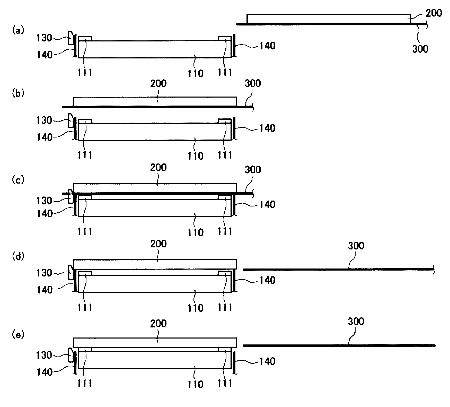
[0250]In this Reference Example, the effect of the positioning operation by the positioning devices130 was evaluated. Specifically, as in Example 1, in accordance with the procedure shown in FIGS. 4(a) to (e), the robot arm 300 was used to transfer the glass substrate 200 to a position above the electrostatic chuck 110, and the bottom sides of the glass substrate 200 were brought into contact with the guide surfaces of the positioning devices 130, followed by lowering the glass substrate 200 by gravity to perform the positioning operation such that the positional relationship between the electrostatic chuck 110 and the glass substrate 200 was put in a proper state. After that, the four corners of the rear surface of the glass substrate 200 were held by the supporting pins 140, the supporting pins 140 and the positioning devices 130 (actually the mask 150 with the positioning devices 130 mounted thereto) were lowered to bring the rear surface of the glass substrate 200 into contact w...


PUM

PropertyMeasurementUnit
holding forceaaaaaaaaaa
angleaaaaaaaaaa
angleaaaaaaaaaa

Abstract

A glass substrate-holding tool employed during the production of a reflective mask blank for EUV lithography includes an electrostatic chuck and a mechanical chuck. A caught and held portion of a glass substrate caught and held by the electrostatic chuck, and pressed portions of the glass substrate pressed by the mechanical chuck are located outside a quality-guaranteed region on each of a film deposition surface and a rear surface of the glass substrate. The sum of a catching and holding force applied to the glass substrate by the electrostatic chuck and a holding force applied to the glass substrate by the mechanical chuck is at least 200 kgf. A pressing force per unit area applied to the glass substrate by the mechanical chuck is at most 25 kgf / mm2.

Description

BACKGROUND OF INVENTION[0001]1. Field of Invention[0002]The present invention relates to a glass substrate-holding tool. The glass substrate-holding tool according to the present invention is useful for holding a glass substrate during the production of a reflective mask blank for EUV (Extreme Ultra Violet) lithography (hereinbelow, referred to as “EUV mask blank” in the specification) to be used for, e.g. the production of semiconductors, and during the production of a functional film-provided substrate for such an EUV mask blank.[0003]Further, the present invention relates to a method for producing an EUV mask blank and a functional film-provided substrate for such an EUV mask blank by employing the glass substrate-holding tool according to the present invention.[0004]2. Discussion of Background[0005]In the semiconductor industry, a photolithography method using visible light or ultraviolet light has been employed as a technique for transferring a fine pattern on a silicon substra...

Claims


Application Information

Patent Timeline
Patent Type & Authority Patents(United States)
IPC IPC(8): H01L21/687C23C14/50G03F1/24H01L21/677H01L21/683
CPCC23C14/50G03F1/24H01L21/67748H01L21/6831H01L21/68728Y10S269/903Y10S269/90G03F1/22G03F1/60G03F1/64
Inventor MITSUMORI, TAKAHIROKINOSHITA, TAKERUISE, HIROTOSHI
Owner ASAHI GLASS CO LTD
Why Eureka
Try Eureka