Mold for thermal nanoimprint lithography, process for fabricating the same, and nanoimprint process using the same

Active Publication Date: 2015-03-10
COMMISSARIAT A LENERGIE ATOMIQUE ET AUX ENERGIES ALTERNATIVES
View PDF13 Cites 3 Cited by
  • Summary
  • Abstract
  • Description
  • Claims
  • Application Information

AI Technical Summary

Benefits of technology

[0075]Because the heating elements of the mold according to the invention may be adapted to each group of patterns notably by modifying the size and/or the shape and/or the density of the heating elements according to the shape and/or the size of the patterns to be printed of each of the groups, this allows groups of patterns to be heated to different temperatures and therefore the viscosity of the layer, of the polymer, resin film to be printed may be locally adjusted in order to ensure homogeneous sinking of the mold into the resin or polymer.
[0076]Thus, for example, <<fine>> patterns may be heated to a lower temperature than <<wide>> patterns and

Problems solved by technology

Taking into account the duration of the other operations associated with the application of this method, i.e. the coating of the material such as a resin, the contacting and the pressing, the removal of the mold, the duration of this temperature cycle therefore limits the yield of this kind of technology.
Further, with silicon molds which are generally applied in the thermal nano-printing technique, alignment between the patterns on the mold and patterns already made on the plate to be printed, is possible but very difficult.
Moreover, this alignment cannot be achieved when the mold and the plate, wafer to be pressed are very close, since it must be possible to position the camera.
This constraint therefore limits the alignment capability.
Typically, obtaining an accuracy of the alignment may be expected, located in a range of few hundred nanometers, which is very insufficient for many applications.
Therefore, the use of silicon molds limits the field of the application of the thermal nanoprinting technology.
But, the making of the mold then remains a problem since, the quartz substrates are more expensive and more difficult to structu

Method used


Image

  • Mold for thermal nanoimprint lithography, process for fabricating the same, and nanoimprint process using the same
  • Mold for thermal nanoimprint lithography, process for fabricating the same, and nanoimprint process using the same
  • Mold for thermal nanoimprint lithography, process for fabricating the same, and nanoimprint process using the same

Examples


Example

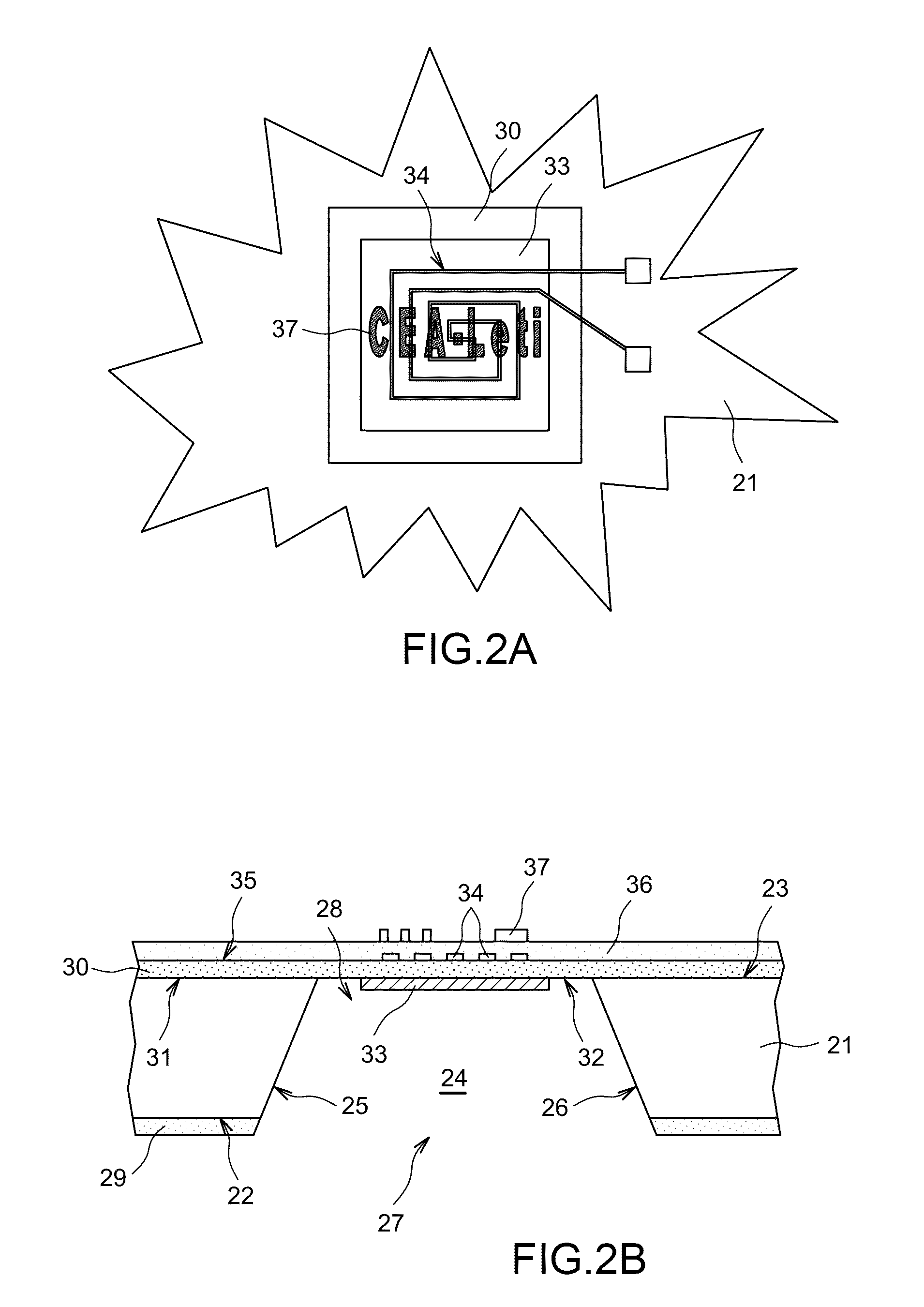
[0145]We shall begin by describing for convenience, the second embodiment of the mold according to the invention which is illustrated in FIGS. 2A and 2B.

[0146]This mold comprises a substrate (21) including a first main surface (22) and a second main surface (23).

[0147]In FIG. 2B, the first (22) and second (23) main surfaces are planar, parallel and horizontal. The first main surface (22) may therefore be defined as a lower surface, while the second main surface (23) may be defined as an upper surface. It is quite understood that this arrangement of the first main surface (22) and of the second main surface (23) is only given as an example and that other arrangements of both of these surfaces may be contemplated.

[0148]The substrate (21) may thus have the shape of a plate or platelet, wafer, comprising two planar, parallel, for example square, rectangular or further circular surfaces (22, 23).

[0149]The thickness of the substrate (21), i.e. the distance between the first main surface (...

Example

[0274]We shall now describe the first embodiment of the mold according to the invention which is illustrated in FIG. 9.

[0275]For the sake of simplification and coherence, the same references as those used in the figures which describe the second embodiment have been used in FIG. 9.

[0276]This mold comprises a substrate (21) including a first main surface (22) and a second main surface (23).

[0277]In FIG. 9, the first (22) and second (23) main surfaces are planar, parallel and horizontal. The first main surface (22) may therefore be defined as a lower surface, while the second main surface (23) may be defined as an upper surface. It is quite obvious that this arrangement of the first main surface (22) and of the second main surface (23) is only given as an example and that other arrangements of both of these surfaces may be contemplated.

[0278]The substrate (21) may thus have the shape of a plate or platelet (wafer) comprising two planar, parallel, for example square, rectangular or fur...

Example

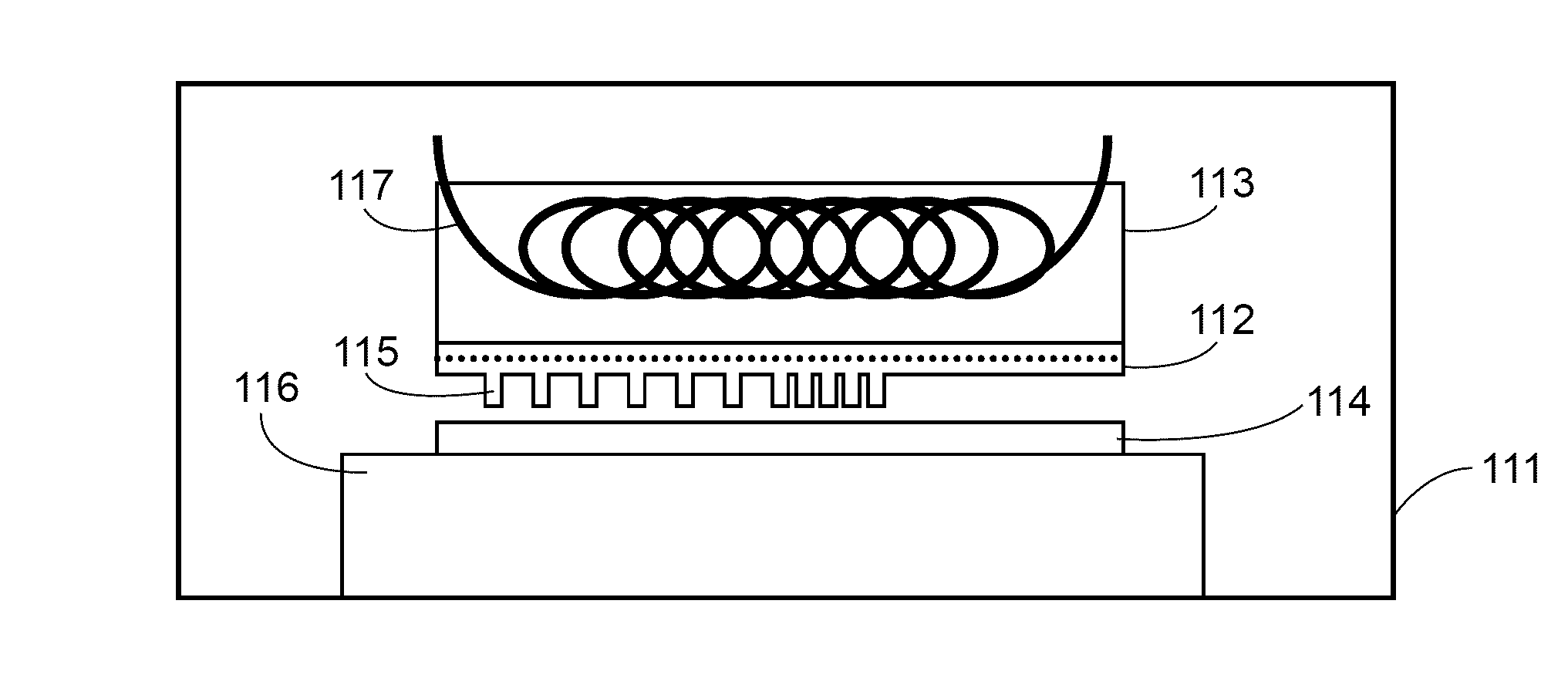
[0326]In a third embodiment, illustrated in FIG. 11C, one or more sources (117) are integrated into the plate support (116).

[0327]Depending on the equipment used and its complexity, one of these embodiments or any combination of two or three of these embodiments may be applied.

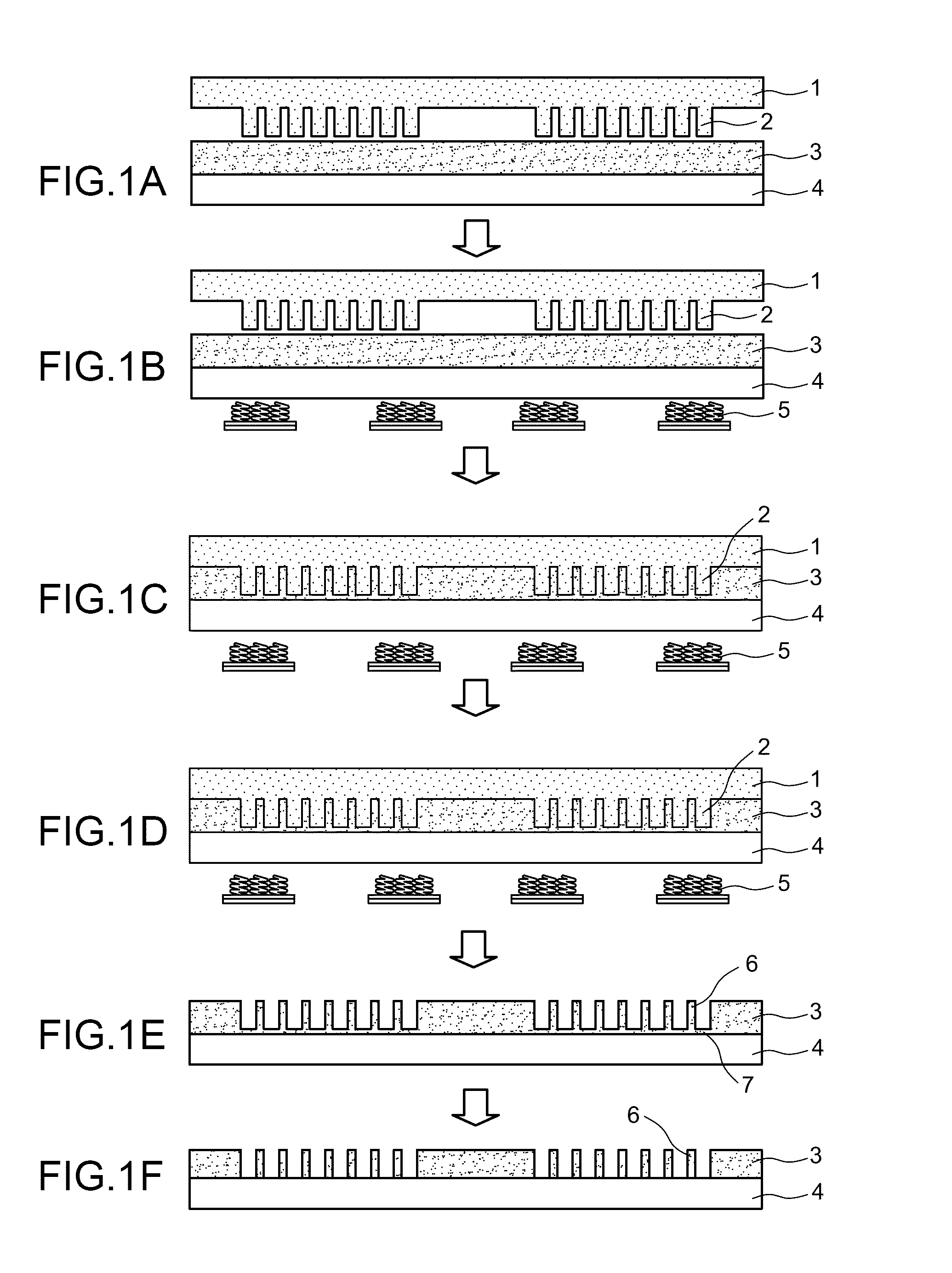
[0328]The mold according to the invention may be used in a method for making a substrate comprising a surface nanostructured by a thermal nanoimprint lithography technique.

[0329]Such a method may for example comprise the following successive steps:

[0330]a) a layer of an organic resin or of a mineral material with a low melting temperature is deposited on a planar surface of a substrate;

[0331]b) the organic resin is heated up to a temperature greater than or equal to its glass transition temperature Tg or its melting temperature, or the mineral material is heated up to a temperature greater than or equal to its melting temperature and the organic resin or liquid mineral material layer is printed with the mold a...


PUM

PropertyMeasurementUnit
Temperatureaaaaaaaaaa
Sizeaaaaaaaaaa
Densityaaaaaaaaaa

Abstract

A heating mold for thermal nanoimprint lithography is disclosed. According to one aspect, the mold includes a resistive heating element and collecting element for collecting the electromagnetic energy of a variable electromagnetic field emitted by a source located outside the mold. The collecting element being connected to the resistive heating element in which the electromagnetic energy is dissipated. A method for manufacturing the mold, a thermal nanoimprint lithography device including the mold, and a a method for preparing a substrate including a surface nanostructured by a thermal nanoimprint lithography technique using the mold is applied are also disclosed.

Description

RELATED APPLICATIONS[0001]This application claims priority to French Patent Application No. 10 1057112 filed Sep. 7, 2010, which is incorporated herein by reference in its entirety.FIELD OF THE INVENTION[0002]The invention relates to a mold for thermal nanoimprint lithography or thermally assisted nanoimprint lithography.[0003]The invention further relates to a method for preparing this mold.[0004]Finally the invention relates to a thermal nanoimprint lithography method which applies this mold.CONVENTIONAL ART[0005]The technical field of the invention may be generally defined as that of Nano-Imprint Lithography (or <<NIL>>).[0006]Nano-imprint lithography combines the critical small dimensions of electron beam lithography and the high yield of optical technology (scanner or stepper), and is a cost-effective technique within the scope of applying high definition lithography.[0007]There exist many types of nanoimprint lithography but the most important ones are thermal nano...

Claims


Application Information

Patent Timeline
IPC IPC(8): A01J21/00B82Y10/00B82Y40/00G03F7/00
CPCG03F7/0002B82Y10/00B82Y40/00
Inventor LANDIS, STEFANNICOLETTI, SERGIO
Owner COMMISSARIAT A LENERGIE ATOMIQUE ET AUX ENERGIES ALTERNATIVES
Why Eureka
Try Eureka