Tissue fastening systems and methods utilizing magnetic guidance

a technology of tissue fastening and magnetic guidance, applied in the field of mitral valve ins, can solve the problems of many types of ailments, dilation (stretching) of the mitral annulus, and incongestive heart failur

Inactive Publication Date: 2015-03-17
EDWARDS LIFESCIENCES CORP
View PDF312 Cites 102 Cited by
  • Summary
  • Abstract
  • Description
  • Claims
  • Application Information

AI Technical Summary

Benefits of technology

[0026]The guide elements may be removed after applying the fastener, and therefore act as a temporary anchor for the fastener delivery device and / or the tissue to be secured. Alternatively, the guide elements, or portions thereof, may be left in place. The guide elements may comprise mechanical fasteners or other types of fasteners such as magnets (i.e., magnetic elements), or combinations thereof. One guide element of the invention comprises first and second spaced apart magnets on the distal support portion of a catheter. Repelling poles of the magnets face each other to create a circumferential virtual pole emanating around the gap formed between the spaced apart magnets. Securing the first and second guide elements together can further comprise magnetically attracting the first and second guide elements together. The same catheter device may be used to direct the second guide element and apply the fastener. In addition, the method can include applying a second fastener to the annulus, coupling the first and second fasteners together, and reducing the distance between the first and second fasteners to reduce the circumference of the annulus. In this case applying the first and second fasteners can occur through the same catheter device. More particularly, the method can involve serially applying the first and second fasteners through one lumen in a catheter device or, as another example, applying the first and second fasteners through different lumens of the same catheter device. In another aspect of the invention, at least one flexible tensile member is used to couple the first and second fasteners together and the flexible tensile member is tensioned to reduce the distance between the first and second fasteners. Shortening the circumferential length of the annulus can further comprise fastening a flexible fabric to the annulus and shortening the circumferential length of the flexible fabric.
[0034]The systems of this invention can include fastener delivery portions comprising at least one spring and drive member each located, for example, at the distal end of a catheter device. Such fastener delivery portions can force the fastener(s) into tissue proximate the annulus. Catheters used in the invention can include a magnet at the distal end for coupling with another magnet located proximate the annulus thereby stabilizing the catheter during delivery of the fastener(s). A lock member may be secured to the flexible tensile member and used to selectively prevent relative movement between the delivered fasteners.
[0035]In another embodiment, a catheter system for modifying an annulus of a heart valve includes a catheter having at least one lumen and first and second fasteners coupled together by a flexible tensile member and adapted to be secured to heart tissue proximate the annulus. A rod is movable between a compact state within the lumen and an expanded state outside of the lumen. The first and second fasteners are further coupled to the rod such that the first fastener is movable along the rod relative to the second fastener by applying tension to the flexible tensile member. The rod may be generally C-shaped in the expanded state so as to follow the annulus. A third fastener may be coupled for movement along the rod and adapted to be secured to heart tissue proximate the annulus. A second flexible tensile member can be secured to the third fastener. The third fastener may then be moved along the rod relative to the second fastener by applying tension to the second flexible tensile member. A magnet can be connected to the rod and adapted to magnetically couple with a magnet in the coronary sinus for stabilizing the position of the rod as the fasteners are secured to the heart tissue.

Problems solved by technology

Congestive heart failure (CHF), which is often associated with an enlargement of the heart, is a leading cause of death.
Many problems relating to mitral valve 20 may occur and may cause many types of ailments.
Enlargement of the heart can result in dilation (stretching) of the mitral annulus.
When the posterior annulus enlarges, it causes the posterior leaflet to move away from the anterior leaflet, causing a gap because the two leaflets no longer form proper coaptation, and this results in leakage of blood through the valve, or regurgitation.
The implantation of a ventricular assist device is often expensive, and a patient with a ventricular assist device must be placed on extended anti-coagulant therapy.
While reducing the risks of blood clots associated with the ventricular assist device is desirable, anti-coagulant therapies may increase the risk of uncontrollable bleeding in a patient, e.g., as a result of a fall, which is not desirable.
While the implantation of a bi-ventricular pacing device may be effective, not all heart patients are suitable for receiving a bi-ventricular pacing device.
Further, the implantation of a bi-ventricular pacing device is expensive, and is generally not effective in significantly reducing or eliminating the degree of mitral regurgitation.
While the use of a pig valve may relatively successfully replace a mitral valve, such valves generally wear out, thereby requiring additional open surgery at a later date.
However, when a mechanical valve is implanted, there is an increased risk of thromboembolism, and a patient is generally required to undergo extended anti-coagulant therapies.
In addition, the use of edge-to-edge stitch 36 is generally not suitable for a patient with an enlarged, dilated heart, as blood pressure causes the heart to dilate outward, and may put a relatively large amount of stress on edge-to-edge stitch 36.
That is, like other conventional procedures, a suture-based annuloplasty procedure is invasive.
While invasive surgical procedures have proven to be effective in the treatment of mitral valve leakage, invasive surgical procedures often have significant drawbacks.
Any time a patient undergoes open-heart surgery, there is a risk of infection.
Opening the sternum and using a cardiopulmonary bypass machine has also been shown to result in a significant incidence of both short and long term neurological deficits.
Further, given the complexity of open-heart surgery, and the significant associated recovery time, people who are not greatly inconvenienced by CHF symptoms, e.g., people at a Class 1 classification, may choose not to have corrective surgery.
In addition, people who most need open heart surgery, e.g., people at a Class 4 classification, may either be too frail or too weak to undergo the surgery.
Unfortunately, since the tissue which forms the CS 46 is relatively delicate, the anchors 52a-c are prone to tear the tissue during the cinching procedure, and the effect on the mitral annulus may be reduced by the position of the coronary sinus up more towards the left atrium rather than directly over the mitral annulus itself.
Other minimally invasive techniques have been proposed and / or developed but have various drawbacks related to such factors as effectiveness and / or cases and accuracy of catheter-based implementation.

Method used


Image

  • Tissue fastening systems and methods utilizing magnetic guidance
  • Tissue fastening systems and methods utilizing magnetic guidance
  • Tissue fastening systems and methods utilizing magnetic guidance

Examples


Embodiment Construction

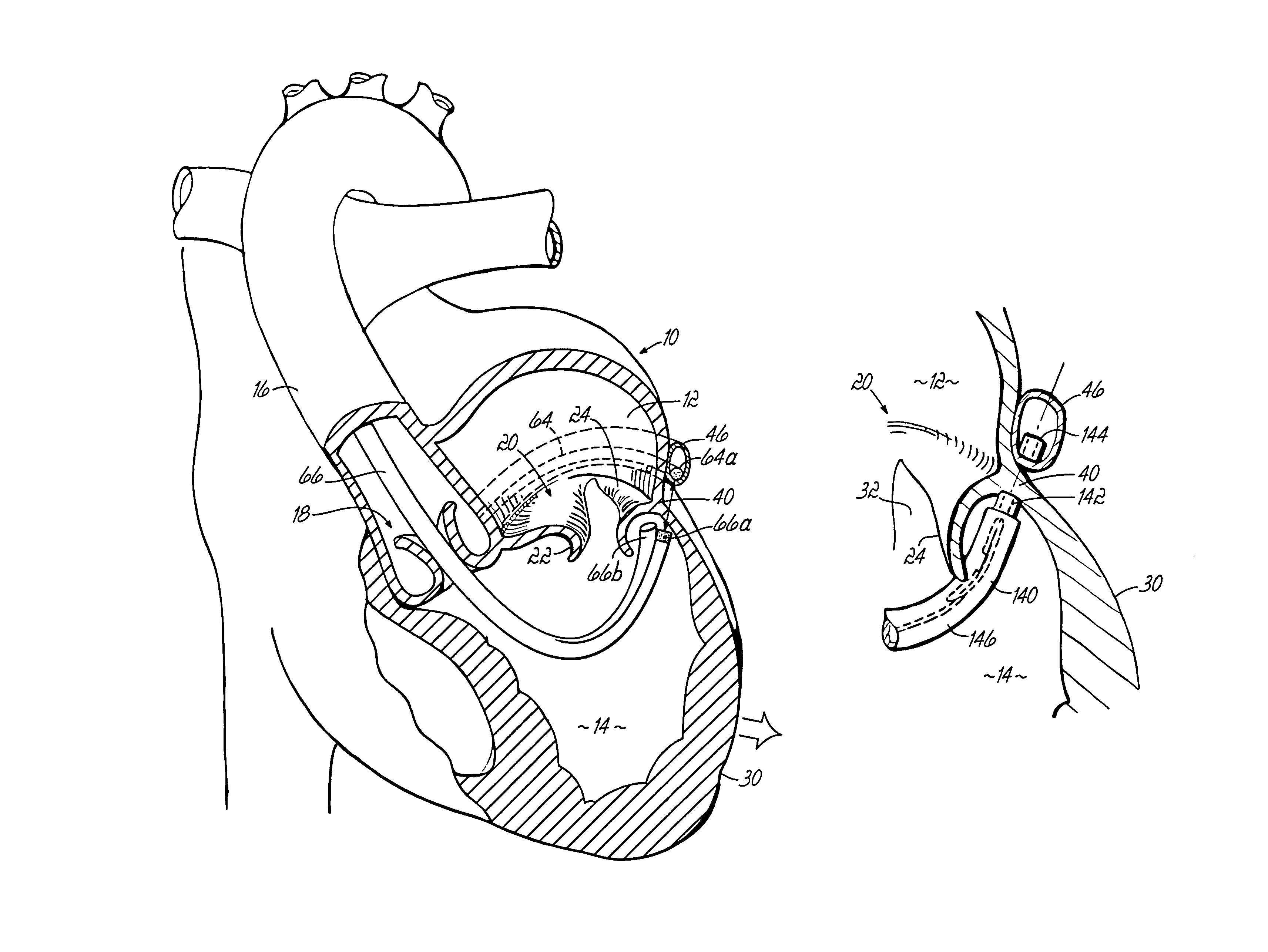
[0113]In this description of illustrative examples, like reference numerals refer to like element throughout the drawings. Like reference numerals with prime (′) marks or double prime (″) marks refer to like structure except for minor differences which will be apparent. FIGS. 1J and 1K illustrate an improved catheter delivered fastener system 50′ which involves placing a permanent fastener or anchor 60 from the CS 46 through the wall of the left atrium 12 proximate annulus 40 for anchoring purposes. This improvement may be applied to the prior cinching method illustrated in FIG. 1I discussed above. The fastener 60 may be deployed and anchored in various manners, including those discussed further below. Because the fastener 60 extends not only through the delicate CS tissue, but also through the thicker tissue of the left atrium 12, secured anchoring takes place and, upon cinching using a flexible tensile member 54, the annulus 40 may be reduced to correct for a prolapsed valve or ot...


PUM


Abstract

Catheter based systems and methods for securing tissue including the annulus of a mitral valve. The systems and methods employ catheter based techniques and devices to plicate tissue and perform an annuloplasty.

Description

CROSS-REFERENCE TO RELATED APPLICATIONS[0001]The present application claims the priority of U.S. Provisional Application No. 60 / 531,855 filed on Dec. 23, 2003 and U.S. Provisional Application No. 60 / 554,314 filed Mar. 18, 2004, the disclosures of which are hereby incorporated herein by reference.[0002]The present application is also a Continuation-In-Part of U.S. Ser. No. 10 / 689,872, filed Oct. 21, 2003 which claims the priority of U.S. Provisional Application Ser. No. 60 / 420,095, filed Oct. 21, 2002. The disclosures of these applications are hereby fully incorporated by reference herein.FIELD OF THE INVENTION[0003]The present invention relates generally to techniques for treating mitral valve insufficiencies such as mitral valve leakage due to prolapse, papillary muscle dysfunction, or annular dilation. More particularly, the present invention relates to systems and methods for treating a leaking mitral valve in a minimally invasive manner. Various aspects of the invention further ...

Claims


Application Information

Patent Timeline
Patent Type & Authority Patents(United States)
IPC IPC(8): A61F2/24A61B17/00A61B17/04
CPCA61B17/0401A61F2/2451A61F2/2466A61F2210/009A61B17/0487A61B2017/00243A61B2017/0496A61B2017/00876A61B2017/0409A61B2017/0414A61B2017/0417A61B2017/0419A61B2017/0464A61B2017/00783A61B17/0469A61B2017/00349A61B2017/0462A61B2017/0472A61B2017/0649A61F2/2445A61B17/0482A61B17/064A61B2017/00398A61B2017/00862A61B2017/0406A61B2017/0454A61B2017/0641A61B2017/0647A61F2002/30079A61F2220/0016A61F2220/0075
Inventor SPENCE, PAUL A.MCNAMARA, EDMAGUIRE, MARK
Owner EDWARDS LIFESCIENCES CORP
Why Eureka
Try Eureka