
Combustion control via homogeneous combustion radical ignition (HCRI) or partial HCRI in cyclic IC engines

a technology of cyclic ic engine and combustion radical ignition, which is applied in the field of thermofluid, can solve the problems of inability to control specific exothermic power and residence time of reacting species, continue to be penalties and limitations associated with not only the conventional versions of these ignition modes, and achieve the effects of reducing required fuel concentration, increasing fuel efficiency, and reducing required hea

Active Publication Date: 2015-04-21
BLANK DAVID A
View PDF44 Cites 11 Cited by
  • Summary
  • Abstract
  • Description
  • Claims
  • Application Information

AI Technical Summary

Benefits of technology

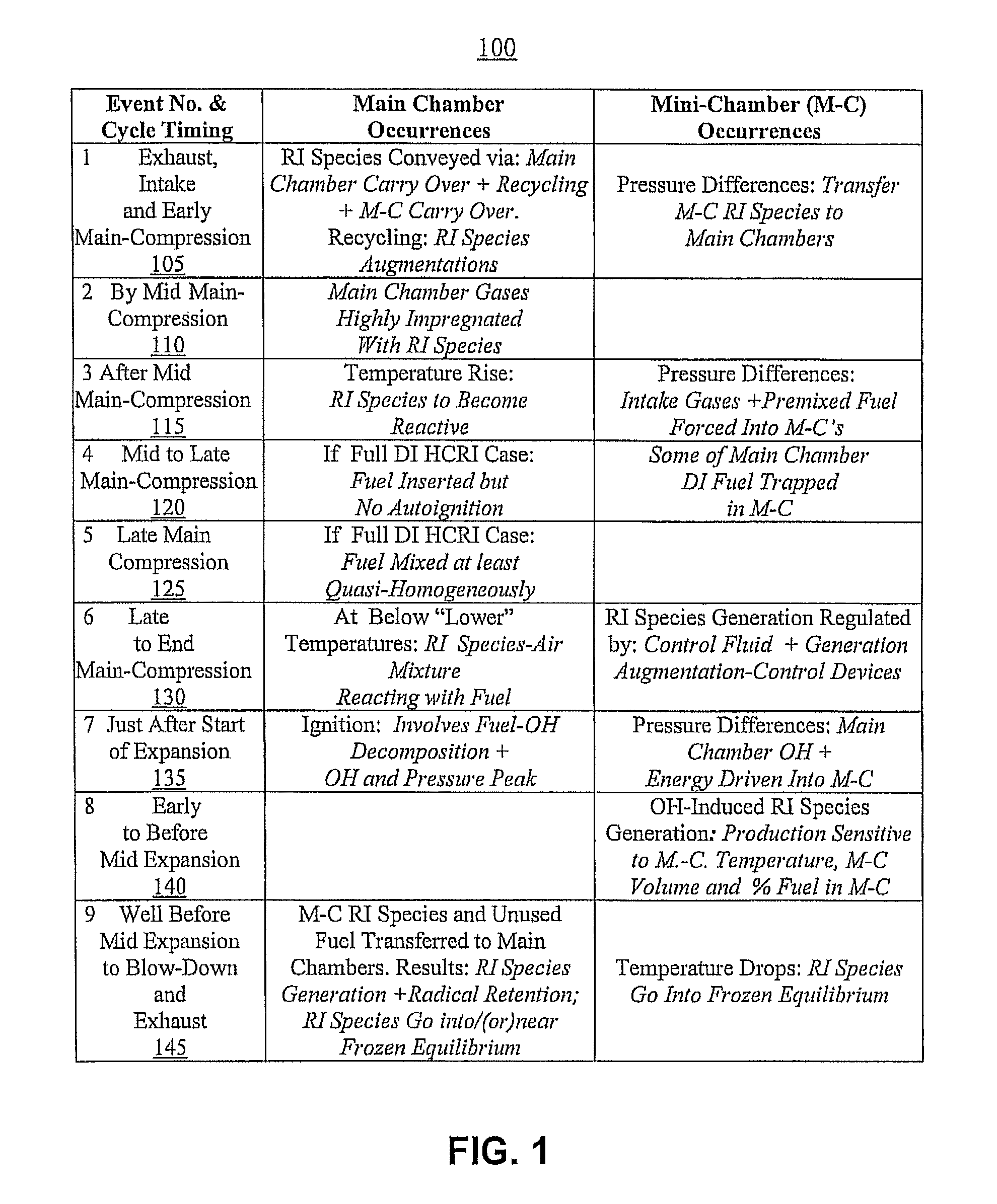
[0025]Another embodiment of the present invention relates generally to a method for increasing fuel efficiency by controlling a reduction in required heat and / or a reduction in required fuel concentrations relative to oxygen concentrations for an ignition of a fuel while simultaneously increasing a compression ratio for the ignition within a main combustion chamber of an engine. The method may include a controlled insertion within a current combustion cycle of a fluid or substance of higher heat of vaporization and higher volatility but lower ignitability than the fuel in order to increase the compression ratio required for self ignition of a mass of the fuel and the fluid (substance) together (compared to a compression ratio required for self ignition with a calorifically equivalent mass of just the fuel). The method may further include providing within the current combustion cycle a plurality of radical ignition species that is generated at least in part in at least one prior combustion cycle at least in part within at least one secondary chamber associated with the main combustion chamber of the engine. The plurality of radical ignition species is generated by at least one OH-induced OH-fuel-decomposition driven chemical-kinetics mechanism. The method may also include directing a portion of the plurality of radical ignition species to the main combustion chamber for use in the current cycle. The method may also further include regulating an accumulation of the portion of the radical ignition species to modulate the ignition of the fuel in the main combustion chamber, whereby the method enables a raising of the compression ratio of the engine while simultaneously lowering the fuel-to-air ratio required for the self ignition of the fuel.
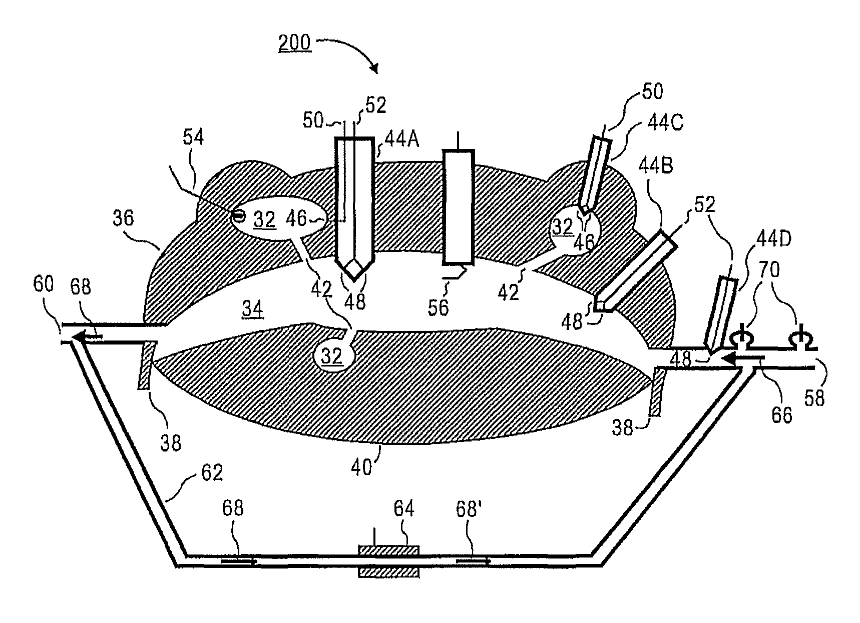
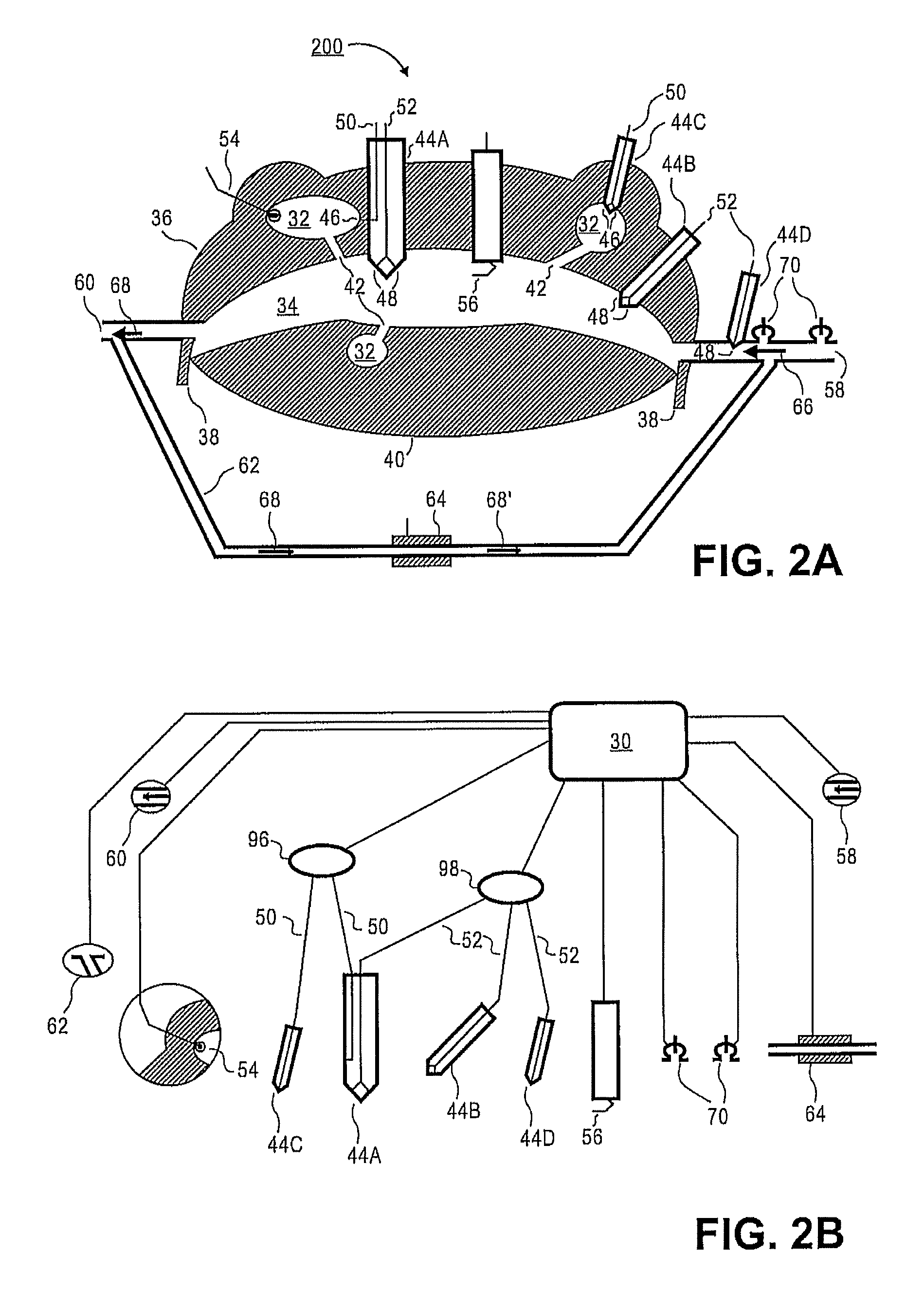
[0027]Yet one more enhanced embodiment relates generally to an apparatus in an internal combustion engine which may include a cylinder, the cylinder further comprising at least one variable volume combustion chamber defined by a work-power producing component moving within a space bounded externally by a cylinder housing. The cylinder is configured to periodically receive a fuel and an air charge and to implement a combustion cycle comprising an intake, main-compression, combustion, power-expansion and exhaust portions phases. The apparatus may additionally include at least one provision for inserting into the cylinder a special fluid (or substance) of higher heat of vaporization and higher volatility but lower ignitability than the fuel, where the provision inserts the special fluid either together or separately from the receiving of the fuel. This is to increase the compression ratio required for self ignition of a combined mass of the fuel and the special fluid (compared the compression ratio required for self ignition of a calorifically equivalent mass of just the fuel). The apparatus may further include at least one mini-chamber arranged about the cylinder housing of the cylinder in proximity with the at least one variable volume combustion chamber, where the mini-chamber is configured to serve as an origination site for a generation of a plurality of radical ignition species. The apparatus may also include at least one connecting conduit configured to couple the at least one mini-chamber with an associated the at least one variable volume combustion chamber, where the at least one connecting conduit is also configured to allow flow of the radical ignition species, the air, the fuel, the special fluid and chemical reaction products in and out of the at least one mini-chamber during various phases of the combustion cycle. The apparatus may further include at least one controller configured to regulate an amount of the plurality of radical ignition species provided to the at least one variable volume combustion chamber for use in the combustion phase and based upon load and speed requirements applied to the engine. The apparatus thereby may enable a raising of the compression ratio of the engine while simultaneously lowering a fuel-to-air ratio required for the self ignition of the fuel.

Problems solved by technology

However, despite many related advances, there continue to be penalties and limitations associated with not only the conventional versions of these ignition modes, but also with newer permutations of these two modes.
However, this front spreads through the main chamber at its own natural speed, and is thus effectively beyond any further control.
Additionally, within this zone (front) of chemical activity, the specific-exothermic power and residence time of the reacting species cannot be controlled.
The rapid expansion within this moving combustion zone (due to the release of the exothermic energy) tends to cause its reacting particles to be expelled prematurely (from the moving front).
Thus, the rate of combustion is diminished and the combustion is incomplete with undesirable emissions.
Conventional enhancements to this process have been generally limited to the efficacy of the air fuel-mixing.
Unfortunately, because it is dependent on fluid-dynamic dispersion of the product kernels in the same cycle, the LAG engine could only be made to operate effectively over a limited portion of the overall engine-operating regime.
Unfortunately, this technology has disadvantages.
One is that it can only provide average overall engine operating-regime optimizations for simultaneous engine efficiency improvements and emission reduction.
Because it must typically be optimized for an engine's overall operating-regime conditions, this piston-based technology produces too many radicals during high loads and not enough radicals during low loads.
Consequently, at high loads, the injection timings must be too late for adequate mixing of the fuel, degrading the degree of homogeneity of the combustion and increasing the production of CO and other pollutants.
Thus, it cannot take advantage of the full potential of RI at all points in the engine's operating regime.
At some operating points it actually lowers engine performance.
However, at certain operating conditions in the PCCI engine there are as yet unresolved problems.
Additionally, due to early heat release before TDC the thermal efficiency may decrease, and due to the faster and earlier combustion the engine's operation may become rough.
Conversely, when the load decreases, ignition timing tends to be retarded.
This may eventually result in misfire, as well as in an increase in emissions.
In this case, if the time available becomes insufficient, misfiring may also occur.
However, if the effective-charge CR (the autoignition CR) is lower than the mechanical CR of the engine, then combustion will start before piston TDC and the engine will knock unacceptably.
If the autoignition CR is higher than the mechanical CR of the engine, then a misfire will occur and the engine will not operate.
Therefore, the primary limitation of TI is the absence of an acceptable means of controlling the initiation of premixed HCCI and SCCI (stratified charge CI) (collectively PCCI) over the possible range of operating conditions (including fuel cetane or octane values, ambient temperatures, loads, engine speeds, etc.) necessary for a practical engine.
However, in their JPIC system, combustion control relies both on reactant composition and fluid mechanics and thus suffers the same restrictions found in the LAG engine.
Thus the Smartplug does not involve RI and its advantages are primarily limited to premixed charge applications with their lower thermal efficiency potentials.
These cannot be effective in high speed and load situations.
Thus neither is capable of providing the control needed to make homogeneous combustion occur and work over the entire engine-operating regime.
However, effective TI prior art is limited both to premixed fuel applications (and thus to lower efficiencies) and to operations over only limited portions of the engine operating regime.
Whereas DI-fuel insertion IC engine variants provide higher efficiency potentials and are not engine operating regime limited, they are unfortunately not capable of homogenous combustion operations.
However, the exercise of control over the combustion in this RI variant is far too limited, and within certain portions of the engine operating regime this variant actually degrades combustion.
Because HCRI potentially lowers the heat of compression required for autoignition, it may lower either the required engine operating compression ratios or the required fuel-to-air ratios needed for combustion (or a combination of both).
However, in certain applications, lower compression ratios may not be wholly desirable for fuels that are relatively easy to ignite.
But while HCCI can not be made to operate an engine over an entire engine operating regime, HCRI may be, potentially making HCRI a process for accomplishing homogenous combustion.
Yet, to avoid conditions leading to engine knocking, fuels such as gasoline may necessitate the use of lower than desired compression ratios for use with HCRI, as they may require the use of lower than optimum compression ratios.

Method used


Image

  • Combustion control via homogeneous combustion radical ignition (HCRI) or partial HCRI in cyclic IC engines
  • Combustion control via homogeneous combustion radical ignition (HCRI) or partial HCRI in cyclic IC engines
  • Combustion control via homogeneous combustion radical ignition (HCRI) or partial HCRI in cyclic IC engines

Examples


Embodiment Construction

[0058]For simplicity and illustrative purposes, the principles of the present invention are described by referring mainly to exemplary embodiments thereof. However, one of ordinary skill in the art would readily recognize that the same principles are equally applicable to, and can be implemented in, all types of combustion engines, and that any such variations do not depart from the true spirit and scope of the present invention. Moreover, in the following detailed description, references are made to the accompanying figures, which illustrate specific embodiments. Electrical, mechanical, logical and structural changes may be made to the embodiments without departing from the spirit and scope of the present invention. The following detailed description is, therefore, not to be taken in a limiting sense and the scope of the present invention is defined by the appended claims and their equivalents.

[0059]An embodiment generally relates to an ignition control process. More particularly, ...


PUM


Abstract

A process is provided for improving combustion control and fuel efficiency in rotary and reciprocating IC engines by enabling leaner combustion at higher compression ratios using less heat for ignition. Embodiments employ secondary chambers of minimal total volume within a cylinder periphery. These chambers communicate with a main chamber via conduits and enable a radical ignition (“RI”) species generation and supply process that starts in earlier cycles to be augmented and used in later cycles. Measures regulate the RI species generated and provided to the main chamber. These species alter dominant chain-initiation reactions of the combustion ignition mechanism. Also employed when preferable are fluids of higher heat of vaporization and volatility but lower ignitability than the fuel. This process improves combustion in radical ignition engines and radical augmented spark and compression ignition engines.

Description

RELATED APPLICATIONS[0001]This application claims priority and benefit of U.S. Provisional Application Ser. No. 61 / 350,939 filed on Jun. 3, 2010, U.S. Provisional Application Ser. No. 61 / 426,503 filed on Dec. 22, 2010 and U.S. Provisional Application Ser. No. 61 / 484,179 filed on May 9, 2011. Further, this application is a continuation-in-part of U.S. patent application Ser. No. 12 / 945,306 filed on Nov. 12, 2010, which is a continuation-in-part of U.S. patent application Ser. No. 12 / 390,800 filed on Feb. 23, 2009, now U.S. Pat. No. 7,832,372, issued Nov. 16, 2010, which is a continuation of U.S. Utility patent application Ser. No. 11 / 695,797, filed Apr. 3, 2007, now U.S. Pat. No. 7,493,886, which claims priority to U.S. Provisional Application Ser. No. 60 / 789,933 filed on Apr. 7, 2006, U.S. Provisional Application Ser. No. 60 / 865,709 filed on Nov. 14, 2006, U.S. Provisional Application Ser. No. 60 / 885,279 filed on Jan. 17, 2007, and U.S. Provisional Application Ser. No. 60 / 892,332 fi...

Claims


Application Information

Patent Timeline
Patent Type & Authority Patents(United States)
IPC IPC(8): F02B19/08F02B19/18F02M25/07F02B19/12F02B53/00F02B53/02F02B55/02F02D35/02F02D41/30
CPCF02B55/02F02B19/12F02B53/02F02D35/02F02D41/3035F02B2053/005Y02T10/125Y02T10/17Y02T10/128F02B19/10F02B19/18F02B2023/085F02D41/0025F02D41/0027F02M26/35F02P15/02Y02T10/12
Inventor BLANK, DAVID A.
Owner BLANK DAVID A
Learn More