Reverse flow regenerative apparatus and method

a heat-regeneration burner and reverse-flow technology, which is applied in lighting and heating apparatus, combustion types, furnaces, etc., can solve the problems of gas leakage around the media bed, if insignificant to the overall efficiency of the apparatus, and achieve the effect of increasing the width of the opening, reducing the risk of gas leakage, and increasing the cross section of solid materials

Active Publication Date: 2015-04-28
NOVELIS INC
View PDF42 Cites 0 Cited by
  • Summary
  • Abstract
  • Description
  • Claims
  • Application Information

AI Technical Summary

Benefits of technology

[0017]This arrangement allows hot waste combustion gases to pass upwardly through the media bed so that any condensable contaminant in the gases condenses to a liquid in the media bed and flows out of the bed under gravity before becoming solid. The liquid contaminant may then be removed from the regenerator from a position below the media bed. Therefore, as hot combustion gases are exhausted from a furnace or the like via the first opening and through the media bed, the condensed contaminants flow under gravity towards the hotter surface of the media bed (the lower surface at the time being heated by the hot combustion gases) rather than the cooler upper surface, and thus have a reduced likelihood of freezing and solidifying before they exit the media bed.
[0028]Another consideration is that, as the width of the openings is increased, particles of the media bed may seat lower into the openings from above, thus presenting a larger cross section of solid material at the upper end of the opening, and thus greater resistance to gas flow. Compensation for this can be made by increasing the size of the particles, but this may affect the overall porosity of the media bed. For example, it is found that when the media bed is made of spheres, e.g. of alumina or other ceramic, having a diameter of one inch (25.4 mm) and the openings have a width of 0.88 inch (22 mm) rather than 0.75 inch (19 mm), the spheres tend to seat lower in the wider openings, lessening the “effective” open area when media is present in the opening. To compensate, larger size spheres of more than 1 inch to 1.5 inch (25.4 to 38 mm) diameter may be used. It is estimated that the larger spheres would increase the effective porosity by about 40%.
[0029]As previously mentioned, the strength of the gas flow during the exhaust phase of the cycle also has an impact on the problem of solid build-up in the bed. The exhaust gas typically has a gas velocity of about 1,890 ft / min (576 m / min) at the media bed / grating interface, and this may be strong enough to impede the flow of salt from the bed. The gas flow at this location is affected directly by the porosity of the grating; i.e. the higher the porosity of the grating, the lower the gas velocity. When the porosity of the grating is increased, the same volume flow of gas moves at a slower rate through what amounts to the equivalent of an opening having a larger cross-sectional area. In theory, in a basic embodiment, the gas flow at the media bed / grating interface may vary anywhere from about 100 to 2,000 ft / min (30.5 to 609.6 m / min), and the media bed would still function effectively. At 100 ft / min (30.5 m / min), good salt drainage could be expected over a broad range of grate porosities, while at 2,000 ft / min (609.6 m / min), the amount of salt draining from the bed would be sharply limited. Combined with an open grating design, a preferred gas velocity is from 800 to 1,300 ft / min (243.8 to 396.2 m / min), a range in which good drainage, would be balanced against optimum furnace / media bed performance.

Problems solved by technology

Of course, in practice, some gas leakage around the media bed, if insignificant to the overall efficiency of the apparatus, may occur.

Method used


Image

  • Reverse flow regenerative apparatus and method
  • Reverse flow regenerative apparatus and method
  • Reverse flow regenerative apparatus and method

Examples


Embodiment Construction

[0045]In the following description, like or equivalent elements throughout the several views of the drawings are identified by the same reference number. However, the use of a single reference number to identify elements in different views should not be taken to imply that the elements are necessarily identical. Any differences will be apparent from the description and from the drawings themselves.

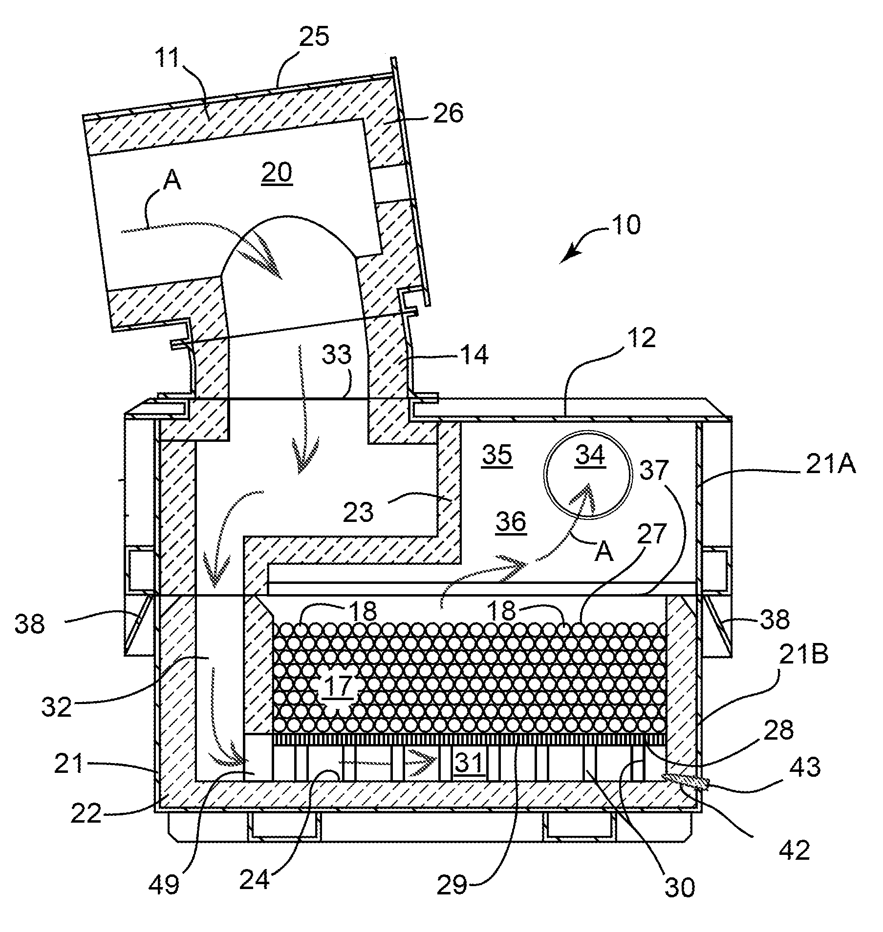
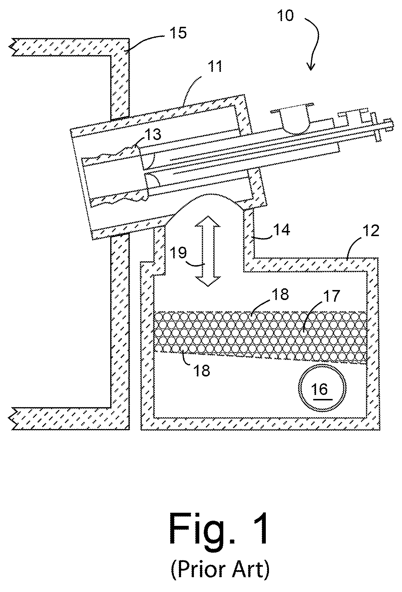
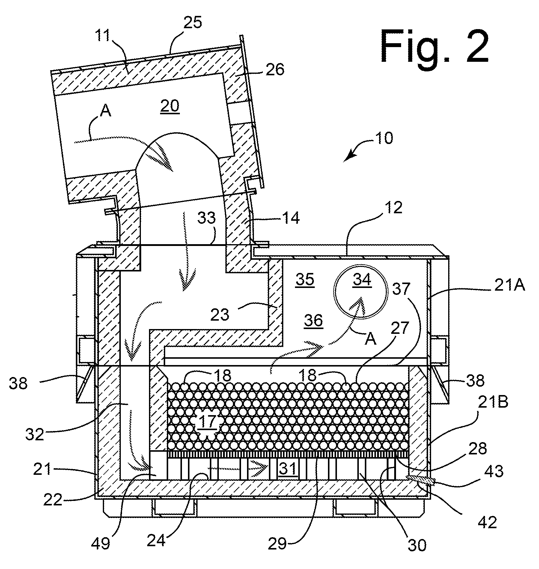
[0046]FIG. 1 shows a conventional heat regenerative fuel burner apparatus of the kind shown in US publication no. 2002-0072020 A1 to Crane et al. mentioned above (the disclosure of which publication is specifically incorporated herein by this reference). As stated earlier, the illustrated burner apparatus works in conjunction with a second identical or similar apparatus. The burner apparatus is indicated generally by reference numeral 10. The apparatus includes a burner housing 11 enclosing a fuel burner 13, and a regenerator 12 interconnected to the burner housing 11 by a tubular element ...


PUM


Abstract

An exemplary embodiment provides a regenerative burner apparatus. The apparatus includes a burner housing having a gas channel and a single-stage heat regenerator equipped with a housing enclosing a fluid-porous heat regenerative media bed. A first gas passageway in the housing directly interconnects the gas channel and the lower surface of the media bed. A second gas passageway in the housing interconnects an opening in the housing communicating with the exterior and the upper surface of the media bed. This arrangement allows hot waste combustion gases to pass upwardly through the media bed so that any condensable contaminant in the gases condenses to a liquid and flows out of the bed under gravity before becoming solid and clogging the bed. The liquid contaminant may then be removed from the regenerator from a position below the media bed.

Description

CROSS-REFERENCE TO RELATED APPLICATION[0001]This application claims the priority right of prior provisional patent application Ser. No. 61 / 460,049 filed on Dec. 23, 2010 by applicants named herein. The entire contents of application Ser. No. 61 / 460,049 are specifically incorporated herein by this reference.BACKGROUND OF THE INVENTION[0002](1) Field of the Invention[0003]This invention relates to reverse flow heat-regenerative burner apparatus used for heating furnaces and the like while limiting heat losses. More particularly, the invention relates to methods and apparatuses that address problems of contamination of the heat exchange media used in such apparatuses.[0004](2) Description of the Related Art[0005]Combustible fuel burners are often employed for heating furnaces intended for melting metals, such as scrap aluminum, glass and other materials. The burners require a supply of combustion air and generate a substantial volume of hot combustion gases that are directed into the f...

Claims


Application Information

Patent Timeline
Patent Type & Authority Patents(United States)
IPC IPC(8): F23L15/00F23L15/02F27D99/00
CPCF27D99/0033F23L15/02Y02E20/34Y02P80/15F27B3/26F27D17/00
Inventor RAUCH, EDWIN L.
Owner NOVELIS INC
Why Eureka
Try Eureka