Engine device

a technology for engine devices and filters, applied in the direction of machines/engines, electric control, mechanical equipment, etc., can solve problems such as engine trouble, and achieve the effects of preventing a deterioration of the clogged state of the filter device, reducing the exhaust gas temperature, and saving fuel consumption

Inactive Publication Date: 2015-05-19
YANMAR POWER TECHNOLOGY CO LTD
View PDF16 Cites 2 Cited by
  • Summary
  • Abstract
  • Description
  • Claims
  • Application Information

AI Technical Summary

Benefits of technology

[0018]According to the invention of claim 1, since in the engine device comprising the engine which serves as the power source, the exhaust gas purifying filter device which is arranged in the exhaust gas path of the engine, and the control means which executes the low rotation control for lowering the engine speed to the predetermined first low rotating speed at a time when the previously set low rotation condition is established, the control means is structured such as to maintain the engine speed at the second low rotating speed which is higher than the first low rotating speed, for suppressing the reduction of the exhaust gas temperature at a time when both of the low rotation condition and the previously set forced regeneration condition are established, the engine speed is maintained at the second low rotating speed (a high idle rotating speed) which is higher than the first low rotating speed (a low idle rotating speed) as long as the filter device is going to be clogged to some extent, even during an execution of the low rotation control which lowers the output of the engine. Thus, it is possible to suppress a reduction of the exhaust gas temperature so as to prevent a deterioration of the clogged state of the filter device, while intending a saving of a fuel consumption and a suppression of a noise due to the low rotation control. In other words, it is possible to suppress a progress of the clogging of the filter device in such a range as not to deteriorate a function of the low rotation control, and it is accordingly possible to enjoy two benefits, that is, a fuel consumption saving and an exhaust gas purification by the working machine. There is achieved such an effect that it is possible to avoid a trouble of a failure caused by the clogging of the filter device because of the execution of the low rotation control.
[0019]Further, according to the invention of claim 2, since in the engine device described in claim 1, the control means is structured such as to lower the engine speed to the first low rotating speed, at a time when only the forced regeneration condition dissolves after setting the engine speed to the second low rotating speed, there is achieved such an effect that it is possible to further improve a fuel consumption reducing effect on the basis of the low rotation control.
[0020]Further, according to the invention of claim 3, since in the engine device described in claim 1 or 2, wherein the control means is structured such as to return the engine speed to the original rotating speed before both of the conditions are established, at a time when both of the low rotation condition and the forced regeneration condition dissolve, after setting the engine speed to the second low rotating speed, it is possible to easily secure the output of the engine only by carrying out an operation for starting the working machine or an operation for driving a working portion. Therefore, there is achieved such an effect that it is possible to securely prevent a problem that the engine rapidly stops due to a lack of the output or an overload, by starting the working machine or driving the working portion under the first low rotating speed (the low idle rotating speed), at a time of returning from the low rotation control.
[0021]According to the invention of claim 4, since in the engine device comprising the engine which serves as the power source, the exhaust gas purifying filter device which is arranged in the exhaust gas path of the engine, and the control means which executes the forced regeneration control of the filter device on the basis of the clogged state of the filter device and the driving state of the engine, the engine device further comprises the forced low rotation operating means for executing the forced low rotation control which forcibly lowers the engine speed to the predetermined low rotating speed, and the control means is structured such as to execute the forced low rotation control in preference at a time of operating the forced low rotation operating means to be turned on, regardless of necessity of the forced regeneration control, the forced regeneration control for raising the output of the engine is not carried out in an overlapping manner, during the execution of the forced low rotation control for lowering the output of the engine. Thus, it is possible to efficiently execute each of the controls without overlapping, in addition to coexistence of two fuel injection controls (the forced low rotation control and the forced regeneration control) which require the mutually opposed actions to the engine. Therefore, it is possible to achieve such an effect that the fuel consumption saving and the exhaust gas purification in the working machine are compatible. Further, there is such an advantage that it is possible to do away with an uncomfortable feeling of an operator due to a rapid change of an engine noise.
[0022]Further, according to the invention of claim 5, since the control means is structured such as to stop the forced low rotation control at a time of operating the moving system operating means or the working system operating means with respect to the working machine on which the engine is mounted, execute the forced regeneration control if the clogged state of the filter device reaches the previously set state at this time, and return the engine speed to the original rotating speed before being lowered if the clogged state of the filter device does not reach the previously set state, it is possible to easily secure the output of the engine only by carrying out the operation for starting the working machine or the operation for driving the working portion, even if an operator fails to carry out the returning operation from the forced low rotation control. Therefore, there is achieve such an effect that it is possible to securely prevent a problem that the engine rapidly stops due to a lack of the output or the overload, by starting the working machine or driving the working portion under the low rotating speed, at a time of returning from the forced low rotation control.
[0023]Further, according to the invention of claim 6, since the control means is structured such as to inform by the informing means which is connected to the control means, at a time when the clogged state in the filter device reaches the previously set state during the execution of the forced low rotation control, there is achieved such an effect that it is possible to comprehend whether the clogging is generated in the filter device so as to call an operator's attention to the clogging of the filter device, even during the execution of the forced low rotation control in which the forced regeneration control is inhibited. Since the forced low rotation control is executed, there is such an advantage that it is possible to avoid a trouble of a failure caused by the clogging of the filter device.

Problems solved by technology

As a result, the soot filter is clogged and an exhaust gas pressure rises up, thereby causing an engine trouble.

Method used


Image

  • Engine device
  • Engine device
  • Engine device

Examples


first embodiment

[0056](1) First Embodiment

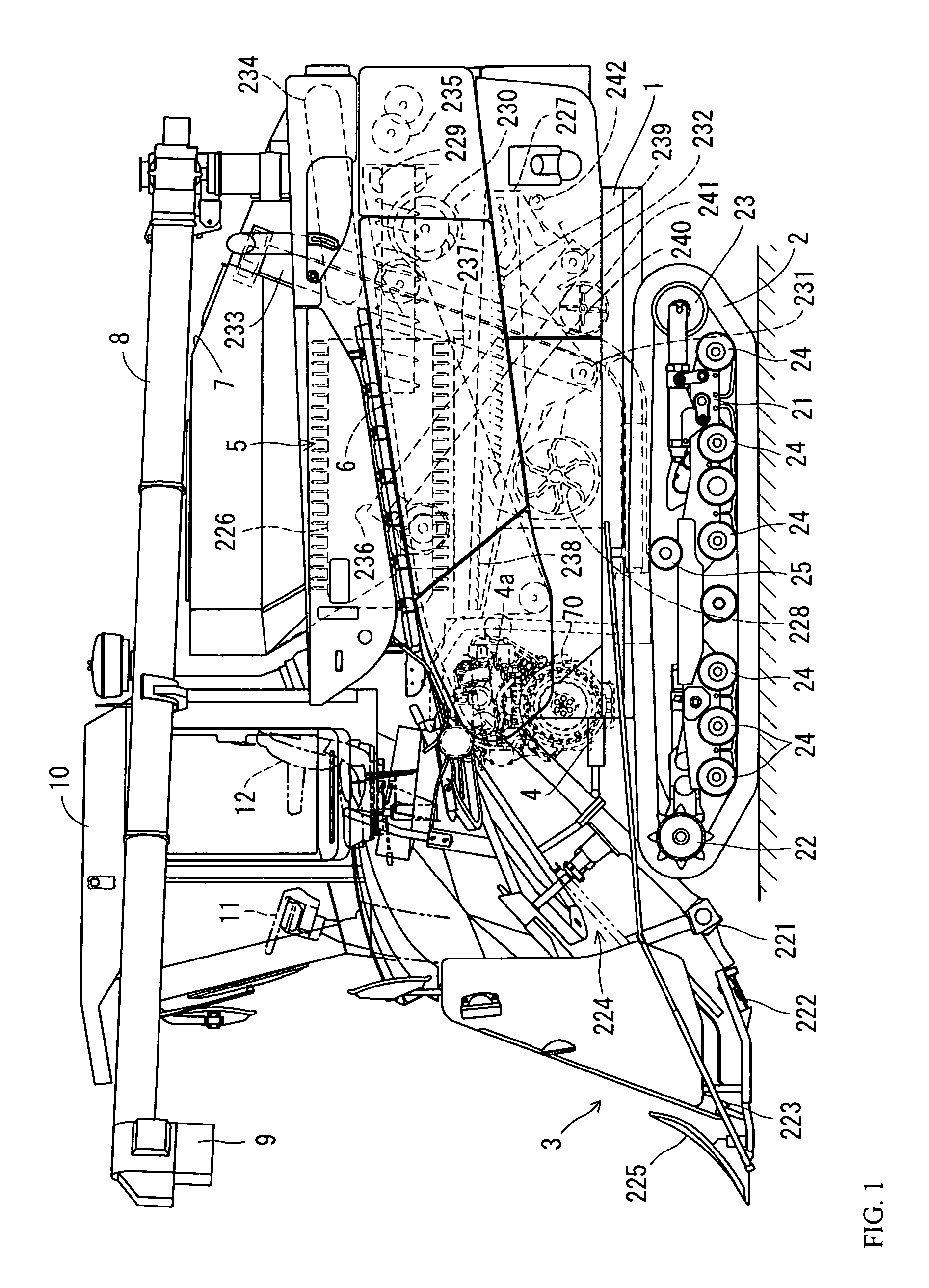
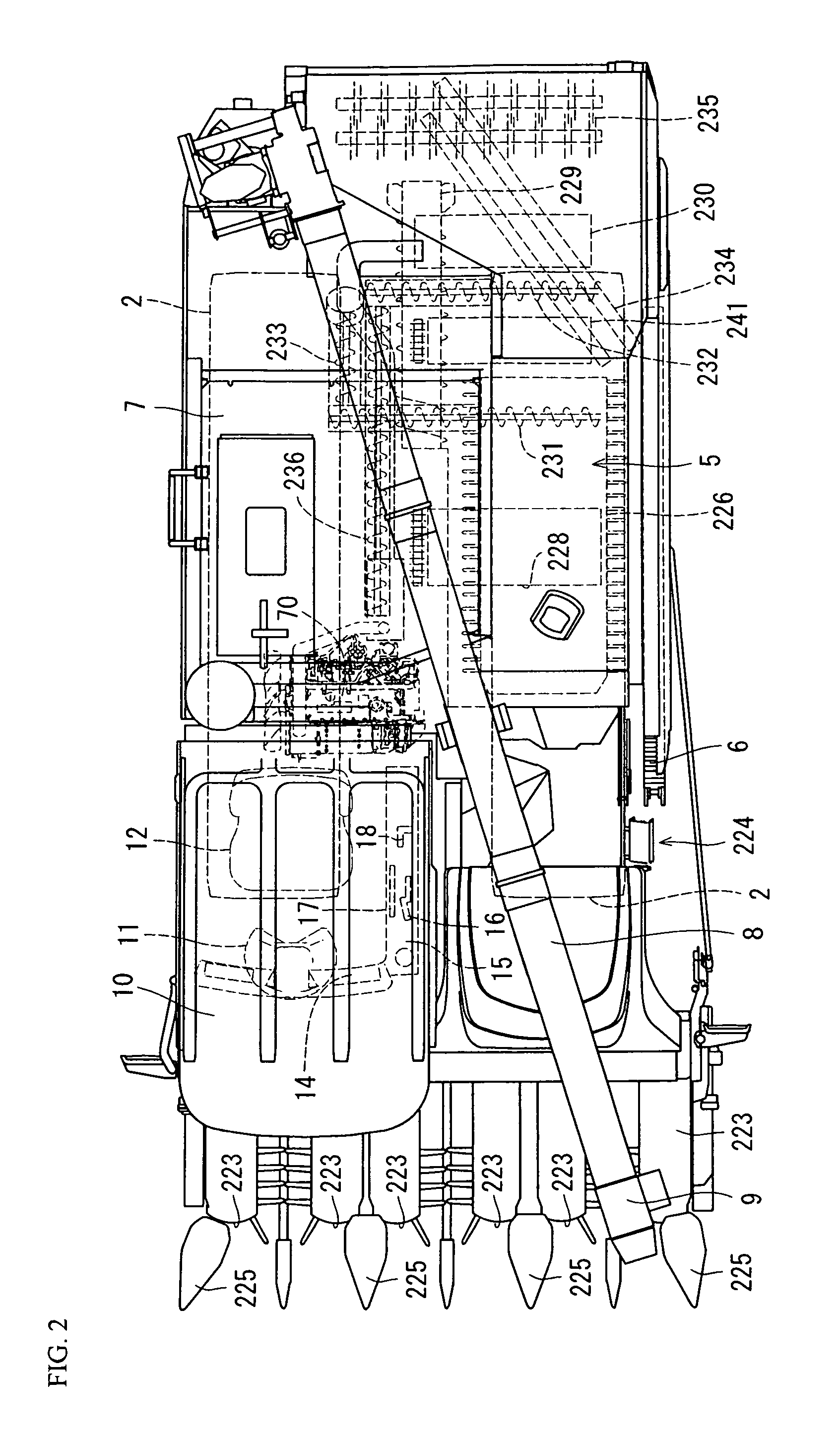
[0057]FIG. 1 to FIG. 12 show a first embodiment in the case that the present invention is applied to a combined harvester serving as a working machine. In this case, in the description relating to a combined harvester in FIG. 1 to FIG. 3, a left side heading for a forward moving direction of a traveling machine body 1 is called simply as a left side, and a right side heading for the forward moving direction is called simply as a right side in the same manner. They are set to references of positional relationships in four directions, and upper and lower in the combined harvester conveniently.

[0058](1-1) Whole Structure of Combined Harvester

[0059]First of all, a description will be given of a whole structure of the combined harvester which corresponds to the first embodiment of a working machine with reference to FIG. 1 to FIG. 3. The combined harvester is provided with a traveling machine body 1 which is supported by a pair of right and left traveling crawle...

second embodiment

[0112](2) Second Embodiment

[0113]FIG. 13 to FIG. 16 show a second embodiment in the case that the present invention is applied to a hydraulic shovel which corresponds to the working machine. In this case, in the description relating to the hydraulic shovel in FIG. 13 and FIG. 14, a left side heading for a forward moving direction of a traveling machine body 1 is called simply as a left side, and a right side heading for the forward moving direction is called simply as a right side in the same manner. They are set to references of positional relationships in four directions, and upper and lower in the hydraulic shovel conveniently.

[0114](2-1) Whole Structure of Hydraulic Shovel

[0115]A description will be given of a whole structure of the hydraulic shovel which corresponds to the second embodiment of the working machine, with reference to FIG. 13 and FIG. 14. As shown in FIG. 13 and FIG. 14, a hydraulic shovel 400 is provided with a crawler type traveling device 402 which has a pair o...

third embodiment

[0131](3) Third Embodiment

[0132]FIG. 17 to FIG. 23 show a third embodiment in the case that the present invention is applied to a hydraulic shovel which mounts an electronic governor type diesel engine thereon. Since the structure of the hydraulic shovel 400 is basically the same as the second embodiment, a detailed description will be omitted by attaching the same reference numerals as the reference numerals of the second embodiment.

[0133](3-1) Whole Structure of Electronic Governor Type Diesel Engine

[0134]A description will be given of a whole structure of an electronic governor type diesel engine 570 with reference to FIG. 17 to FIG. 21. In this case, in the description relating to the diesel engine 570, an installation side of an intake manifold 573 of the diesel engine 570 which is directed rearward with respect to the hydraulic shovel 400 is called simply as a rear side of the diesel engine 570, and an installation side of an exhaust manifold 571 of the diesel engine 570 which...


PUM


Abstract

In an engine device provided with an engine which serves as a power source, an exhaust gas purifying filter device which is arranged in an exhaust gas path of the engine, and control means which executes a low rotation control for lowering an engine speed to a predetermined first low rotating speed at a time when a previously set low rotation condition is established, the control means is structured such as to maintain the engine speed at a second low rotating speed which is higher than the first low rotating speed, for suppressing a reduction of an exhaust gas temperature at a time when both of the low rotation condition and a previously set forced regeneration condition are established.

Description

TECHNICAL FIELD[0001]The present invention relates to an engine device which is mounted to a working machine (for example, an agricultural machine, a construction machine, a marine vessel or the like).BACKGROUND ART[0002]Conventionally, in a working machine such as a combined harvester or a hydraulic shovel, there has been employed a technique of a so-called automatic low rotation control (an auto deceleration control) which automatically lowers an engine speed to a low idle rotating speed under a predetermined condition so as to achieve a low fuel consumption and a low noise (refer to patent documents 1 and 2). For example, in the patent document 1, there is disclosed such a matter that an engine speed is lowered to a low idle rotating speed if a grain threshing clutch connecting and disconnecting a power transmission to a grain threshing device is in an off state and a main shift lever for carrying out a shift operation of a traveling machine body becomes in a neutral state, under...

Claims


Application Information

Patent Timeline
Patent Type & Authority Patents(United States)
IPC IPC(8): F01N3/02B66F9/075E02F9/20F01N3/021F01N13/00F01N13/18F02D41/02F02D41/08
CPCF02D41/029B66F9/07595E02F9/2066E02F9/2095F01N3/0211F01N13/1855F02D41/0205F02D41/08F01N13/0097F01N2470/02F01N2470/18F01N2470/24F01N2590/08F02D41/0245Y02T10/20F02D29/02Y02T10/12
Inventor NOMA, YASUO
Owner YANMAR POWER TECHNOLOGY CO LTD
Why Eureka
Try Eureka