Air cooler and method for operation of an air cooler

a technology of air cooler and air density, which is applied in the direction of indirect heat exchangers, machines/engines, light and heating apparatus, etc., can solve the problems of reducing air density, reducing some gains achieved, and increasing so as to reduce emissions, increase combustion output, and increase the density of intake air

Active Publication Date: 2015-05-26
FORD GLOBAL TECH LLC
View PDF15 Cites 4 Cited by
  • Summary
  • Abstract
  • Description
  • Claims
  • Application Information

AI Technical Summary

Benefits of technology

[0002]Compressors are used in engine intake systems to increase the density of the intake air. Consequently, the combustion output may be increased, emissions may be decreased, and / or fuel economy may be increased. However, compressing intake air also increases the temperature of the intake air. This increase in air temperature decreases air density, thereby diminishing some of the gains achieved via compression of the intake air. Therefore, air coolers positioned downstream of compressors may be used to decrease the temperature of compressed intake air in boosted engines. Air coolers may also be used in conjunction with other systems in the vehicle such as exhaust gas recirculation (EGR) systems to decrease the temperature of the exhaust gas delivered to the intake system.
[0003]Charge air coolers may be designed for specific engine applications. Specifically, the size and geometry of air flow passages in air coolers may be sized for a specific engine or vehicle. When the air coolers are uniquely sized for an engine, the applicability of the air cooler is decreased. For example, if a specified air cooler were used in another engine or vehicle configuration, the engine may experience misfires due to condensation build up caused by the mis-sizing. As a result, combustion efficiency may be decreased. Furthermore, misfires may be exacerbated when the intake air is humid, a large amount of torque is requested by the vehicle operation (e.g., open throttle conditions), and / or during a downshift in a transmission.
[0005]In this way, an air cooler line may be provided for a number of vehicles, thereby increasing the applicability of the air cooler line and decreasing manufacturing costs. The size and geometry of the air flow deflectors may be adjusted to achieve desired air-flow characteristics in each of the air coolers via differences in the flow deflector selected. In this way, manufacturing costs and complexity can be reduced, while still decreasing condensation build-up, if desired. When condensation is decreased in the air coolers, mis-fires in the engine are reduced and the air cooler's reliability is increased.
[0006]In one example, the plurality of air flow conduits in the first air cooler and the plurality of air flow conduits in the second air cooler may be identical in size and geometry. In this way, the air flow conduits are standardized across the air cooler line, enabling the manufacturing costs of the line to be further decreased.

Problems solved by technology

However, compressing intake air also increases the temperature of the intake air.
This increase in air temperature decreases air density, thereby diminishing some of the gains achieved via compression of the intake air.
For example, if a specified air cooler were used in another engine or vehicle configuration, the engine may experience misfires due to condensation build up caused by the mis-sizing.
As a result, combustion efficiency may be decreased.
Furthermore, misfires may be exacerbated when the intake air is humid, a large amount of torque is requested by the vehicle operation (e.g., open throttle conditions), and / or during a downshift in a transmission.

Method used


Image

  • Air cooler and method for operation of an air cooler
  • Air cooler and method for operation of an air cooler
  • Air cooler and method for operation of an air cooler

Examples


Embodiment Construction

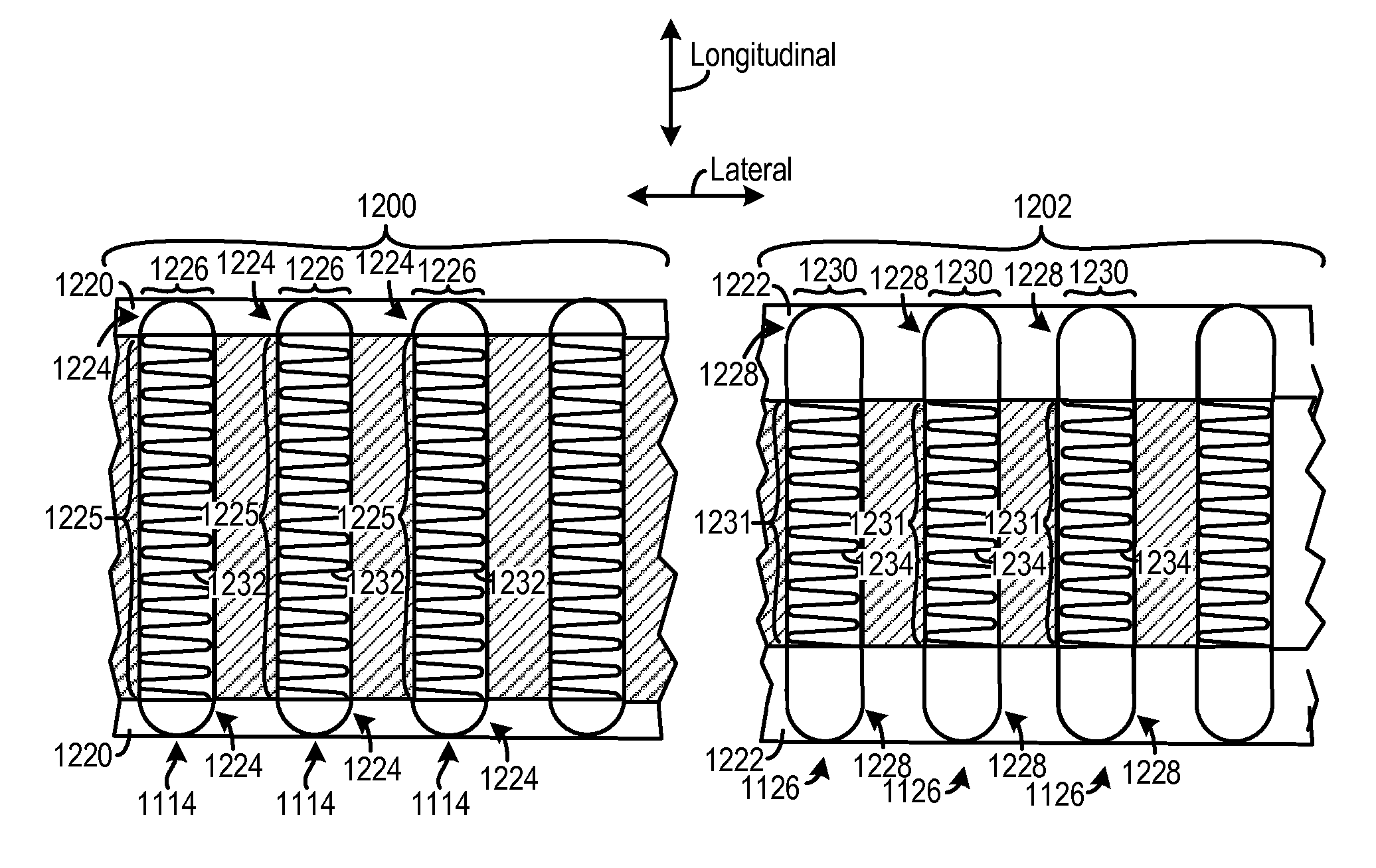
[0018]An air cooler line is described herein. The air cooler line may include two air coolers each having a plurality of air flow conduits with a similar size and shape. The two air coolers may each include an air flow deflector extending across a portion of the inlets of the respective air flow conduits. The air flow deflectors may differ in size and / or shape. Thus, the unobstructed portions of the inlets of the air flow conduits may vary between the two air coolers. In this way, the air flow conduits may be standardized across air cooler while the air flow deflectors may be modified to achieve desired air flow characteristics in each air cooler. In this way, the size and shape of the air coolers may be adjusted for different engines sizes, types, etc., thereby increasing the air cooler lines applicability. As a result, manufacturing cost of the air coolers in the air cooler line may be reduced when the air coolers in the line can be used in a wide range of engine types, sizes, etc...


PUM


Abstract

An air cooler line is provided. The air cooler lines includes a first air cooler having a plurality of air flow conduits, each of the air flow conduits including an inlet, and a first air flow deflector extending across peripheral portions of the inlets and fixedly coupled to the air flow conduits and a second air cooler having a plurality of air flow conduits, each of the air flow conduits including an inlet, and a second air flow deflector extending across peripheral portions of the inlets and fixedly coupled to the air flow conduits, the second air flow deflector differing in at least one of size and geometry than the first air flow deflector.

Description

FIELD[0001]The present disclosure relates to an air cooler in an intake system of on engine.BACKGROUND AND SUMMARY[0002]Compressors are used in engine intake systems to increase the density of the intake air. Consequently, the combustion output may be increased, emissions may be decreased, and / or fuel economy may be increased. However, compressing intake air also increases the temperature of the intake air. This increase in air temperature decreases air density, thereby diminishing some of the gains achieved via compression of the intake air. Therefore, air coolers positioned downstream of compressors may be used to decrease the temperature of compressed intake air in boosted engines. Air coolers may also be used in conjunction with other systems in the vehicle such as exhaust gas recirculation (EGR) systems to decrease the temperature of the exhaust gas delivered to the intake system.[0003]Charge air coolers may be designed for specific engine applications. Specifically, the size a...

Claims


Application Information

Patent Timeline
Patent Type & Authority Patents(United States)
IPC IPC(8): F01P1/00F02B29/04
CPCF01P1/00F02B29/0456F02B29/0406Y02T10/146Y02T10/121F02B29/0412F02B29/0418F02B29/0431F02B37/007Y02T10/12
Inventor NORMAN, KRISTOFOR ROBERTYAMADA, SHUYA SHARKPALM, JIM RAYMONDLADD, JOHN R.KRAMER, MICHAEL THOMASTYLER, JIM
Owner FORD GLOBAL TECH LLC
Why Eureka
Try Eureka