
Polymer dissolution equipment suitable for large fracturing operations

Active Publication Date: 2015-06-30
S P C M SA
View PDF10 Cites 54 Cited by
  • Summary
  • Abstract
  • Description
  • Claims
  • Application Information

AI Technical Summary

Benefits of technology

[0024]One of the constraints lies in the fact that there is no device, at the site of operations, which makes it possible to empty the polymer solutions from the dissolution tanks. Consequently, the equipment must be moved with the tanks full, it being possible however for the amount of powder to be adjusted at the end of operation. This also has the advantage of allowing an immediate start-up of the equipment after travelling.
[0025]The Applicant has developed improved equipment that makes it possible to solve this problem and to significantly improve the performances of existing installations.
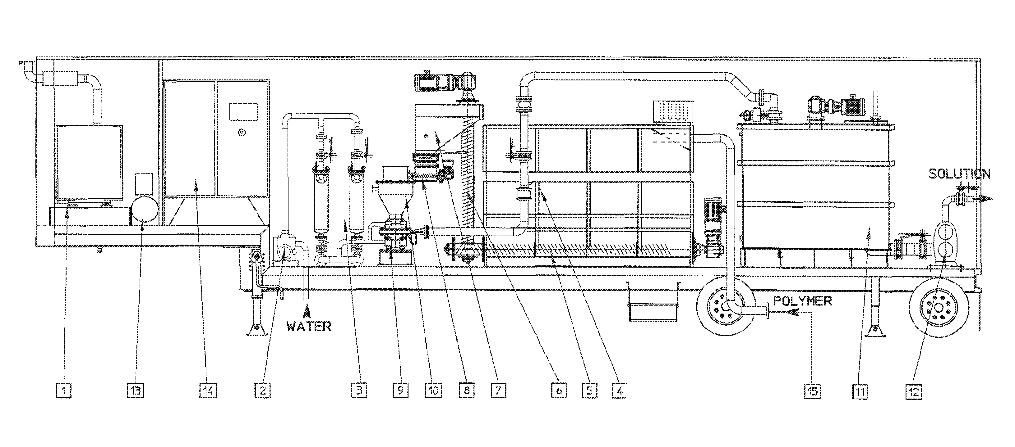
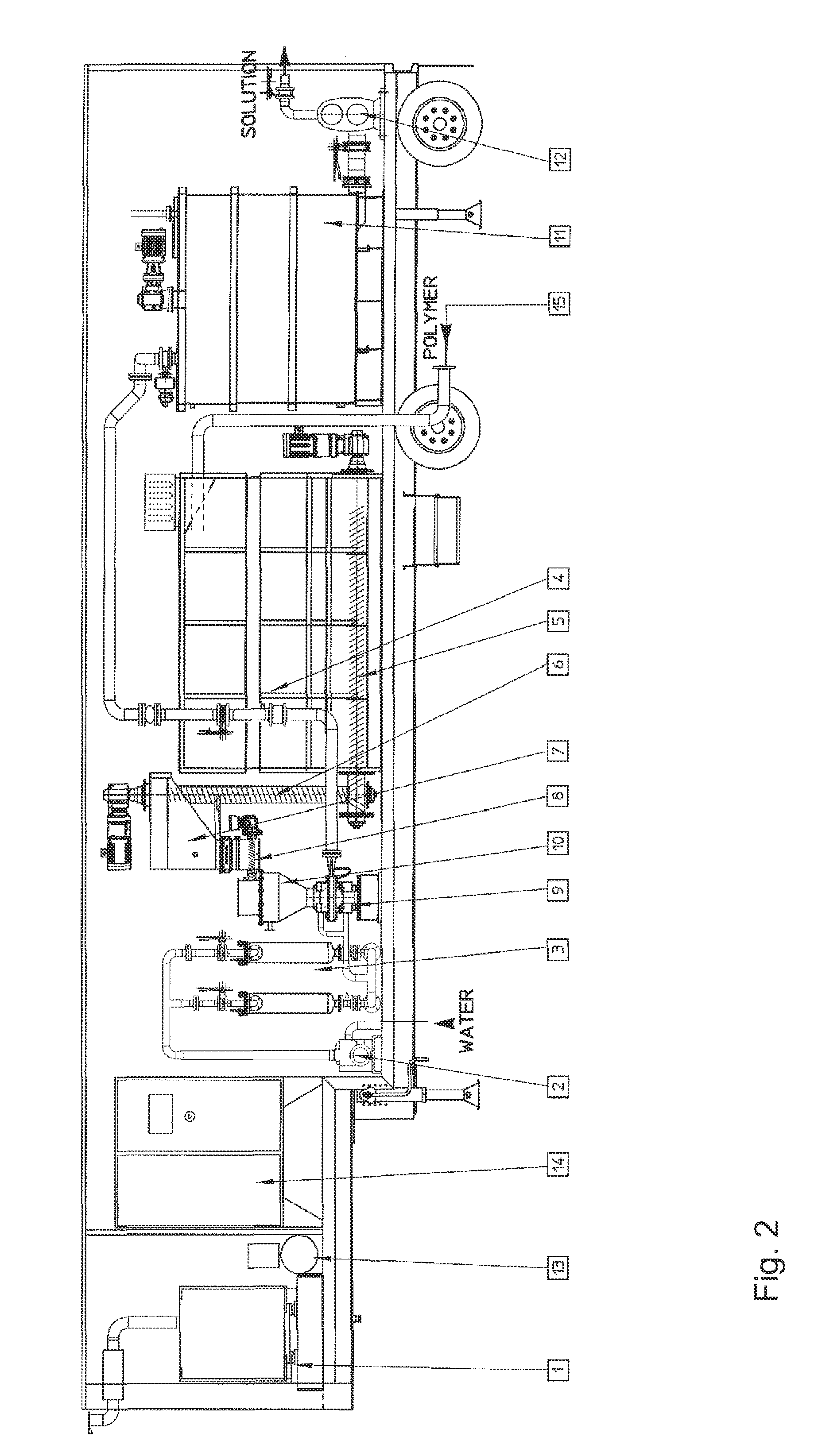
[0046]The dispersing and grinding device allows a hydraulic grinding of the polymer. It has the great advantage of dispersing very large amounts of polymers while greatly decreasing the size of the equipment and accelerating the dissolution of the polymer by wet grinding. This enables very large injections of polymer from equipment of limited volume.
[0050]A dispersing and grinding device similar to that used in the invention was described by the Applicant in document WO 2008 / 107492 for enhanced oil recovery (EOR) applications. This dissolution device, referred to as PSU (polymer slicing unit), is advantageously that sold under the name PSU 300 Plus, which makes it possible to meter out 100 to 600 kg of polymer per hour. These amounts are in accordance with those needed in current fracturing operations. The diameter of the rotor-stator of the polymer dissolution device is preferably greater than 200 mm. In the majority of cases, the PSU operates intermittently, depending on the level of the dissolution tanks at a standard flow rate of 300 kg / hour. It is, however, suitable for much higher spot demands of polymer. The water is fed, into the PSU, at the primary circuit generally at 10 m3 / h and at the secondary circuit from 0 to 20 m3 / h depending on the required concentration and viscosity. The polymer concentration is preferably 20 g / liter. On the other hand, when concentrated brines are used, the effect of the salts on the viscosity makes it possible to increase the concentration to 30 g / liter while keeping the viscosity of the polymer solution below 10 000 cps, enabling easy pumping.
[0055]Passage through the PSU makes it possible to decrease the dissolution time by 20 to 30% on the largest particle sizes and by slightly less on the smaller particle sizes.
[0059]The implementation of the equipment according to the invention in the process according to the invention makes it possible to reduce the fracturing injection pressure while limiting the friction of the fluid in the injection pipes.

Problems solved by technology

One of the constraints lies in the fact that there is no device, at the site of operations, which makes it possible to empty the polymer solutions from the dissolution tanks.

Method used


Image

  • Polymer dissolution equipment suitable for large fracturing operations
  • Polymer dissolution equipment suitable for large fracturing operations
  • Polymer dissolution equipment suitable for large fracturing operations

Examples


Embodiment Construction

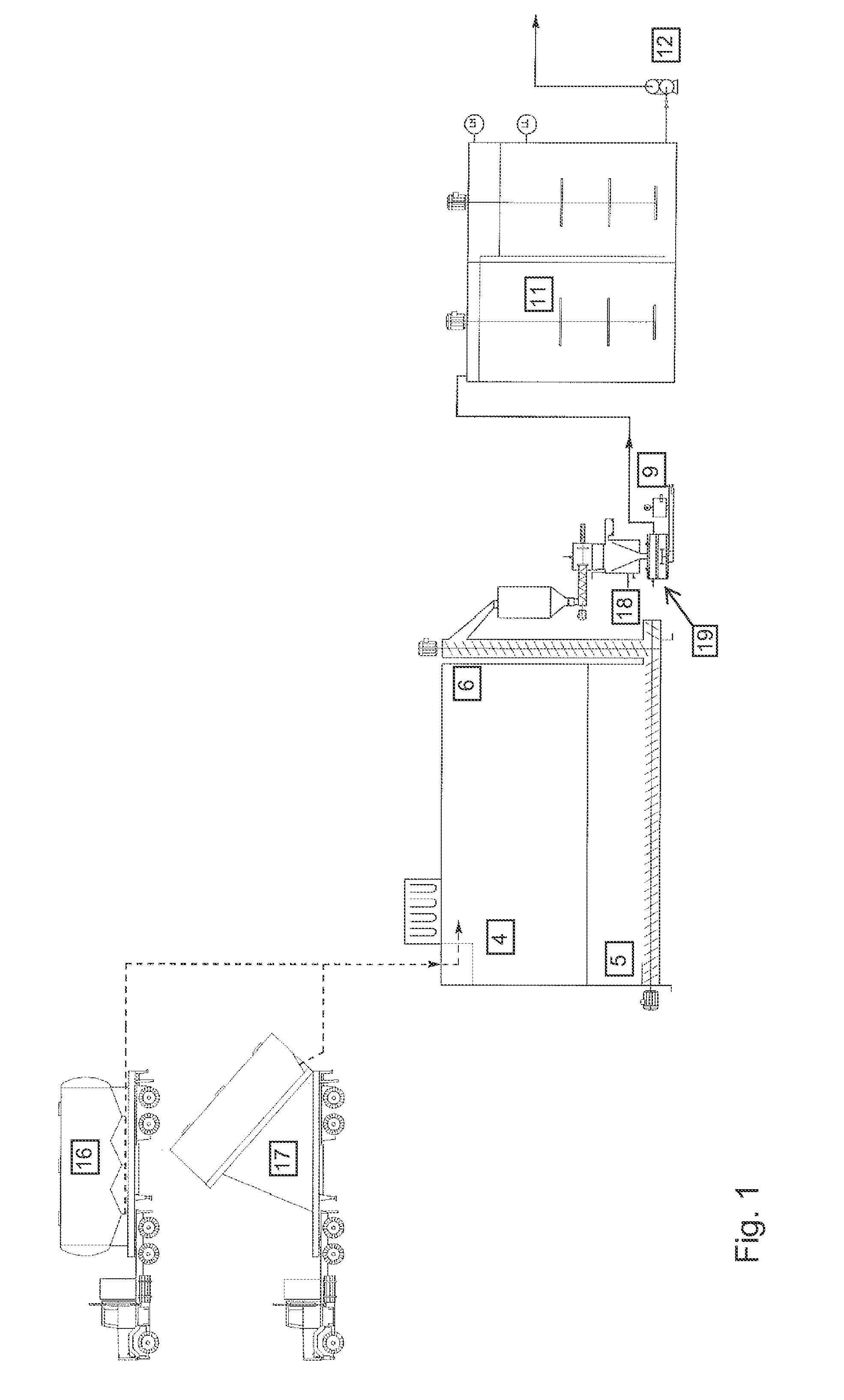
[0071]As already stated, the space available for the equipment that is the subject of the invention is generally limited, it is therefore impossible to install a cylindro-conical silo. The storage silo (4) illustrated by FIG. 2 is horizontal, of parallelepipedal shape and has a base in the shape of a dihedron. Located in this dihedron is a discharge screw (5) which feeds a lifting screw (6) for feeding the PSU with powder polymer by gravity. The lifting screw may optionally be replaced by a pneumatic conveyor.

[0072]This silo is fed pneumatically by a road tanker that transports the polymer, with emptying via cones (16) or a tipping chassis (17). The feeding of the silo with powder polymer may take place before or during operation, depending on the volumes required. But the apparatus transports enough polymer in powder form (2 to 3 tonnes for example) for an immediate start-up.

[0073]The storage silo has a volume greater than or equal to 5 m3, preferably greater than or equal to 10 m3...


PUM

PropertyMeasurementUnit
weightaaaaaaaaaa
weightaaaaaaaaaa
volumeaaaaaaaaaa

Abstract

Compact and transportable equipment that can be used for fracturing operations on gas or oil fields, includes, successively, a silo for storing polymer in powder form, a feed hopper of a polymer metering device, a device for metering out the powder polymer, a device for dispersing and grinding the polymer, and at least two volumetric pumps enabling the injection and metering of the polymer solution obtained in the mixer used for supplying at least one high-pressure fracturing pump.

Description

CROSS-REFERENCE TO RELATED APPLICATIONS[0001]The present Application claims priority of French Patent Application No. 1254119 filed on May 4, 2012, the content of which is incorporated herein by reference.FIELD OF THE INVENTION[0002]The field of the invention is the recovery of gas or oil and more particularly the hydraulic fracturing of gas or oil wells by injection of a fracturing fluid comprising a polymer.BACKGROUND OF THE INVENTION[0003]Document WO 2010 / 020698 describes equipment used for storing, dispersing and dissolving polymers in powder form, more particularly based on acrylamide. The polymer solution is then metered out and used in hydraulic fracturing operations intended for the production of shale gas or dispersed petroleum.[0004]This equipment has significant operating constraints since fracturing operations assemble numerous vehicles (lorries, trailers), sometimes more than 100, comprising electrical generators, transportation of pumps, mixers, devices for dissolving ...

Claims


Application Information

Patent Timeline
Patent Type & Authority Patents(United States)
IPC IPC(8): B02C23/18B01F7/00E21B43/26E21B21/06B01F13/00B01F15/02B01F3/12
CPCB01F7/00758B02C23/18E21B43/26E21B21/062B01F13/004B01F15/0235B01F3/1221B01F23/53B01F27/271B01F33/5023B01F35/71731E21B43/2607
Inventor NICHOLS, PETERBOND, MARSHALL
Owner S P C M SA
Learn More