Blood vessel ultrasonic image measuring method
a blood vessel and ultrasonic technology, applied in ultrasonic/sonic/infrasonic image/data processing, instruments, applications, etc., can solve problems such as difficult to follow movement and lack of skill, and achieve the effect of facilitating positioning, facilitating accurate acquisition of blood vessel diameter, and simple and easy positioning
- Summary
- Abstract
- Description
- Claims
- Application Information
AI Technical Summary
Benefits of technology
Problems solved by technology
Method used
Image
Examples
first embodiment
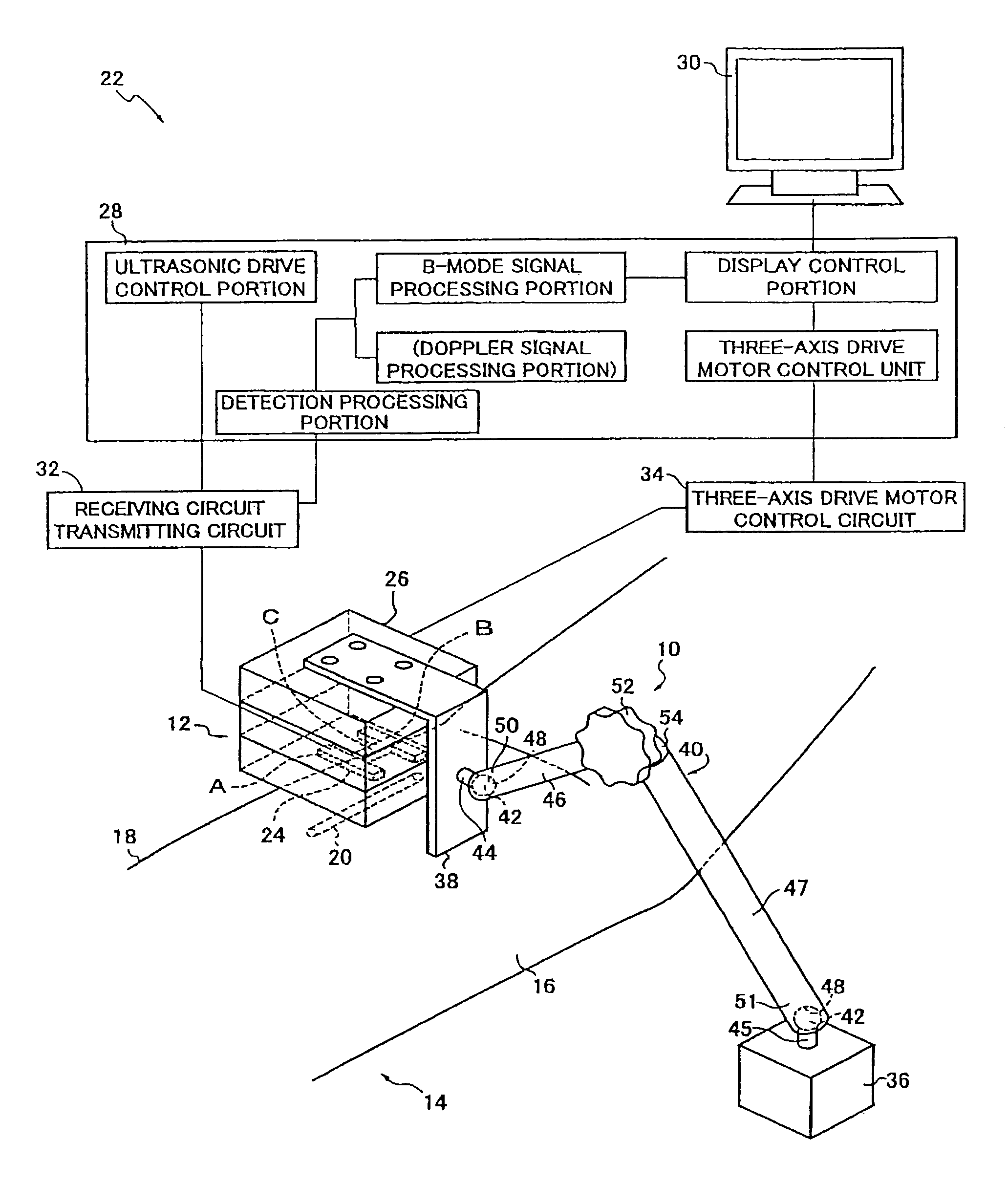
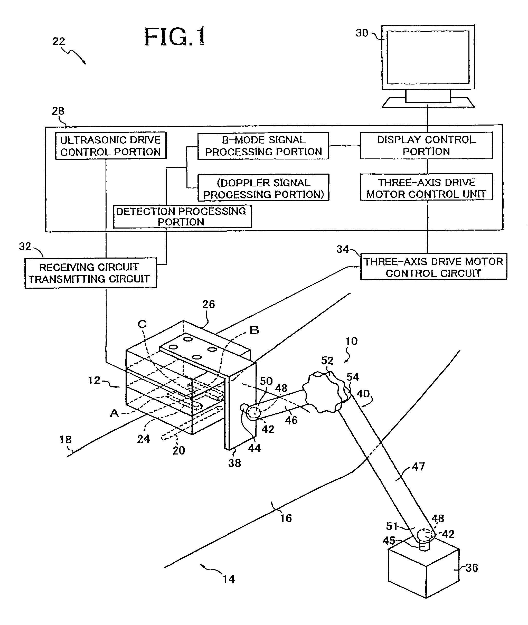
[0089]FIG. 1 is a diagram for explaining an overall configuration of a blood vessel ultrasonic image measuring apparatus 22 using a hybrid probe unit 12 held by a sensor holder 10 to measure a cross-section image (short axis image) or a longitudinal-section image (long axis image) of a blood vessel 20 located immediately below skin 18 from the top face of the skin 18 of an upper arm 16 of a living body 14.
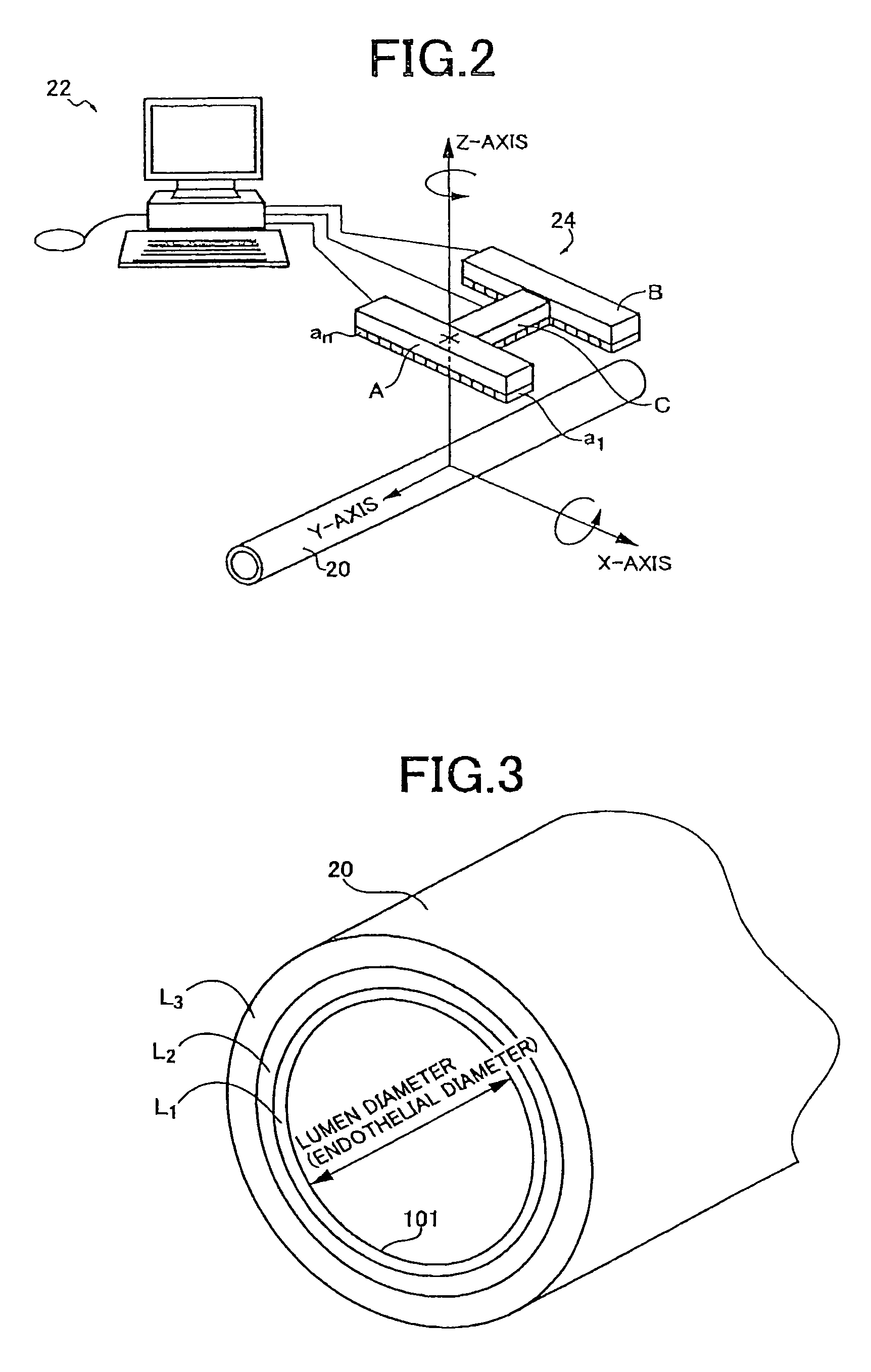
[0090]The hybrid probe unit 12 acts as a sensor for detecting biological information related to the blood vessel, i.e., a blood vessel parameter and includes an H-shaped ultrasonic probe 24 made up of two lines of a first short axis ultrasonic array probe A and a second short axis ultrasonic array probe B parallel to each other and a long axis ultrasonic array probe C linking the longitudinal center potions thereof on one flat surface, i.e., a flat probing surface 27, and a multiaxis driving device (positioning device) 26 for positioning the ultrasonic probe 24. The first short axi...
second embodiment
[0115]Another embodiment of the present invention will then be described. In the description of the following embodiment, the portions overlapping with the embodiment are denoted by the same reference numerals and will not be described.
[0116]FIG. 25 is a diagram for explaining exemplary configurations of the ultrasonic probe and the monitor screen display in another embodiment of the present invention. The hybrid probe unit 12 of this embodiment includes an H-shaped ultrasonic probe 102 made up of two lines of the first short axis ultrasonic array probe A and the second short axis ultrasonic array probe B parallel to each other and rotated around the X-axis such that directions F orthogonal to the ultrasonic emitting surfaces of the ultrasonic transducers a1 to an configured by linear arrangement in the X-axis direction are respectively tilted by predetermined angle α and angle β relative to the Z-axis; and the long axis ultrasonic array probe C configured by linearly arranging the ...
third embodiment
[0120]FIGS. 26 and 27 are flowcharts for explaining a portion of a relevant part of the control operation of the electronic control device 28 in another embodiment of the present invention. Although the artery pattern recognition is performed at steps depicted in the flowcharts of FIGS. 10 and 11 in the embodiment, if the electronic control device 28 includes a Doppler signal processing portion, the artery pattern recognition is performed at steps depicted in the flowcharts of FIGS. 26 and 27 instead of FIGS. 10 and 11. In FIG. 26, at step S26, the ultrasonic oscillation and scanning are started and the convergent ultrasonic beam is emitted from the first short axis ultrasonic array probe A, the second short axis ultrasonic array probe B, and the long axis ultrasonic array probe C and is also scanned. At step S27, an image pattern similar to the standard template TM1 is searched by using the template matching technique in the first short axis image display area G1. At S28, the match...
PUM
 Abstract
Description
Claims
Application Information
 - R&D
- Intellectual Property
- Life Sciences
- Materials
- Tech Scout
- Unparalleled Data Quality
- Higher Quality Content
- 60% Fewer Hallucinations
Browse by: Latest US Patents, China's latest patents, Technical Efficacy Thesaurus, Application Domain, Technology Topic, Popular Technical Reports.
© 2025 PatSnap. All rights reserved.Legal|Privacy policy|Modern Slavery Act Transparency Statement|Sitemap|About US| Contact US: help@patsnap.com


