Submerged combustion melting processes for producing glass and similar materials, and systems for carrying out such processes

a technology of glass and similar materials, applied in the field of submerged combustion melters, can solve the problems of violent turbulence of molten materials, difficult monitoring, and inability to use melter control signals from these sensors, and achieve the effect of reducing or eliminating the problems associated with the molten material

Active Publication Date: 2015-08-04
JOHNS MANVILLE CORP
View PDF99 Cites 61 Cited by
  • Summary
  • Abstract
  • Description
  • Claims
  • Application Information

AI Technical Summary

Benefits of technology

[0011]In accordance with the present disclosure, methods and systems for carrying out the methods are described that reduce or eliminate problems associated with temperature sensor failure in monitoring and / or controlling submerged combustion melters. The methods and systems described herein are relevant to the full range of materials that could be melted with submerged combustion technology.

Problems solved by technology

Using submerged combustion burners produces violent turbulence of the molten material, which may include unmelted material as well as gases.
Frequently, one or more of these phenomena may result in undesirably short life of temperature sensors and other components used to monitor a submerged combustion melter's operation, making monitoring difficult, and use of signals from these sensors for melter control all but impossible for more than a limited time period.
Given that long melter life, and control of the melter during that life are goals for submerged combustion melters and sensors, this failure of sensors is a significant detriment to those goals.
Rue, “Energy-Efficient Glass Melting—The Next Generation Metter”, Gas Technology Institute, Project No. 20621 Final Report (2008) noted that, in submerged combustion melters using oxy-fuel burners to melt glass precursors, one of the most difficult measurements to make is the actual melt temperature.
In one try in a small melter, platinum-clad thermocouples failed when exposed directly to the melt after a short time period because of the interaction with oxy-fuel flame.
However, there is no teaching or suggestion that accurate melt temperature may be indirectly measured and used to control operation of the melter to achieve a desired actual melt temperature.
It is therefore undesirable to superheat the melt because this increases the heat flux through the walls (and frozen melt layer).
Even with these improvements, however, it is not clear if these temperature sensors would stand the rigors of highly turbulent submerged combustion melters.
As noted above by Rue, the interaction with oxy-fuel flames would no doubt be severely detrimental to these sensors as well.

Method used


Image

  • Submerged combustion melting processes for producing glass and similar materials, and systems for carrying out such processes
  • Submerged combustion melting processes for producing glass and similar materials, and systems for carrying out such processes
  • Submerged combustion melting processes for producing glass and similar materials, and systems for carrying out such processes

Examples


embodiment 1

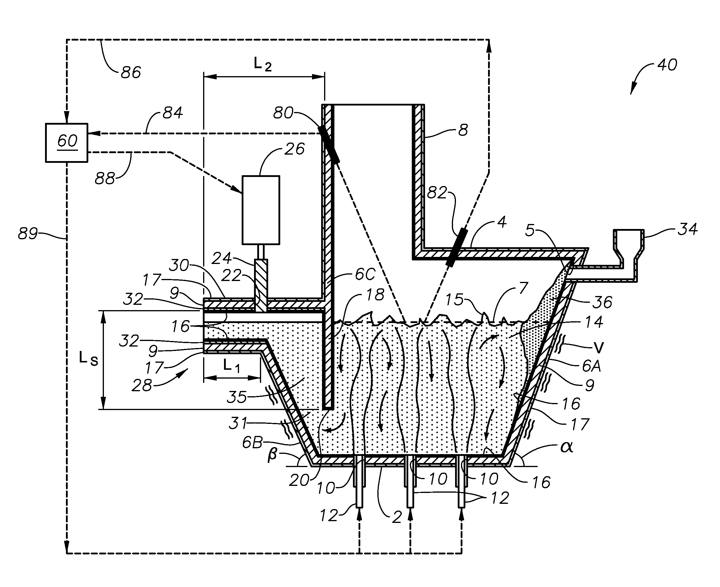
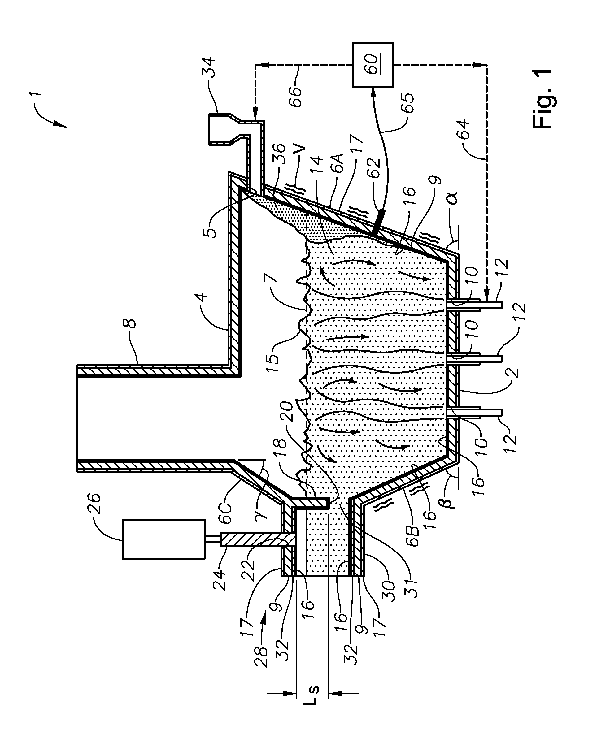
[0052]System embodiment 1 further includes an exhaust stack 8, and openings 10 for floor-mounted submerged combustion burners 12, which create during operation a highly turbulent melt indicated at 14. In certain embodiments, burners 12 are positioned to emit combustion products into molten glass in the melting zone 14 in a fashion so that the gases penetrate the melt generally perpendicularly to floor 2. In other embodiments, one or more burners 12 may emit combustion products into the melt at an angle to floor 2, where the angle may be more or less than 45 degrees, but in certain embodiments may be 30 degrees, or 40 degrees, or 50 degrees, or 60 degrees, or 70 degrees, or 80 degrees.

[0053]The initial raw material can be introduced into the melter of system 1 on a batch, semi-continuous or continuous basis. In some embodiments, a port 5 is arranged at end 6A of the melter through which the initial raw material is introduced by a feeder 34. In some embodiments a “batch blanket”36 may...

embodiment 250

[0068]Still referring to FIG. 11, the conditioning channel of embodiment 250 may include several sections, for example a second section 122, third section 124, fourth section 126, and fifth section 128 arranged in series, each section having a roof, floor, and sidewall structure connecting its roof and floor, and defining a flow channel for conditioning molten glass flowing therethrough. Sections 122, 124, 126, and 128 may be divided by a series of skimmers, first skimmer 133, second skimmer 135, third skimmer 137, and fourth skimmer 139, each extending generally substantially vertically downward a portion of a distance between the roof and floor of the channel, with a final skimmer 141 positioned between fifth channel section 128 and a forehearth 149. The number of sections and the number of skimmers may each be more or less than five. Forehearth 149 may have one or more forming outlets denoted by dashed boxes 151, 153, on its underneath side, such as bushings, gob cutters, and the...

embodiment 100

[0077]FIGS. 3, 5, 8, 10, 12, 14, and 15 are logic diagrams illustrating processes in accordance with the present disclosure, with FIG. 3 illustrating logically a general process, and FIGS. 5, 8, 10, 12, 14, and 15 corresponding to the system embodiments illustrated schematically in FIGS. 1, 4, 6, 9, 11, and 13, respectively. It should be emphasized that all steps of the various process embodiments need not be carried out in series or succession. Embodiment 100 of FIG. 3 includes the steps of feeding at least one partially or wholly vitrifiable material into a feed inlet of a melting zone of a melter vessel comprising a floor, a ceiling, and a wall connecting the floor and ceiling at a perimeter of the floor and ceiling, the melter vessel comprising a feed opening in the wall or ceiling and an exit end comprising a melter exit structure for discharging molten material formed in the melting zone, the melter vessel comprising at least one fluid-cooled refractory panel in its floor, cei...


PUM

PropertyMeasurementUnit
angleaaaaaaaaaa
angleaaaaaaaaaa
angleaaaaaaaaaa

Abstract

Processes of controlling submerged combustion melters, and systems for carrying out the methods. One process includes feeding vitrifiable material into a melter vessel, the melter vessel including a fluid-cooled refractory panel in its floor, ceiling, and / or sidewall, and heating the vitrifiable material with a burner directing combustion products into the melting zone under a level of the molten material in the zone. Burners impart turbulence to the molten material in the melting zone. The fluid-cooled refractory panel is cooled, forming a modified panel having a frozen or highly viscous material layer on a surface of the panel facing the molten material, and a sensor senses temperature of the modified panel using a protected thermocouple positioned in the modified panel shielded from direct contact with turbulent molten material. Processes include controlling the melter using the temperature of the modified panel. Other processes and systems are presented.

Description

STATEMENT REGARDING FEDERALLY SPONSORED RESEARCH OR DEVELOPMENT[0001]This invention was made with government support under contract number DE-FC36-03GO13092 awarded by the United States Department of Energy. The government has certain rights in the invention.THE NAMES OF THE PARTIES TO A JOINT RESEARCH AGREEMENT[0002]The parties to the above-mentioned government contract were Gas Technology Institute, Fluent, Inc., Praxair, Inc., AC Leadbetter & Sons Inc., and Combustion Tec / Eclipse, and a consortium of the following parties: Corning Incorporated, Gas Technology Institute, Johns Manville, PPG Industries, Inc., Schott North America, Regional Research and Development, Duryea, a Division of Schott North America, Inc., Owens Corning Corporation, and the Glass Manufacturing Industry Council.BACKGROUND INFORMATION[0003]1. Technical Field[0004]The present disclosure relates generally to the field of combustion furnaces and methods of use, and more specifically to submerged combustion melte...

Claims


Application Information

Patent Timeline
Patent Type & Authority Patents(United States)
IPC IPC(8): C03B5/24C03B5/44C03B5/20C03B5/167C03B5/04C03B7/06C03B3/02C03B5/235
CPCC03B5/04C03B5/167C03B5/205C03B5/2356C03B5/24C03B5/44C03B7/06C03B3/023C03B2211/70C03B2211/22Y02P40/50
Inventor CHARBONNEAU, MARK WILLIAM
Owner JOHNS MANVILLE CORP
Why Eureka
Try Eureka