Methods for precision optical frequency synthesis and molecular detection

a technology of optical frequency synthesis and molecular detection, applied in the direction of optical radiation measurement, interferometric spectrometry, instruments, etc., can solve the problem of not being efficiently coupled into high-finesse enhancement cavities

Inactive Publication Date: 2015-08-04
IMRA AMERICA
View PDF14 Cites 4 Cited by
  • Summary
  • Abstract
  • Description
  • Claims
  • Application Information

AI Technical Summary

Benefits of technology

[0006]An aspect of the present invention features methods and systems for simultaneous line narrowing of cw lasers, as well as referencing the desired emission wavelength to a frequency comb laser. The beat frequency between an individual comb tooth from the frequency comb laser and the emission frequency of a cw laser is detected with and derived from a detector which receives a filtered output from the comb laser. The signal is fed forward to an acousto-optic frequency shifter (AOFS) downstream from the cw laser to produce a cw laser output which is frequency shifted and locked to the individual comb tooth. Such an arrangement allows for rapid corrections of the emission frequency of the cw laser without the use of a high bandwidth electronic feedback loop. Any slow drifts of the cw laser frequency can further be compensated by a feedback loop that coarsely stabilizes this beat frequency. Additional arbitrary frequency offsets between the cw laser output frequency and the frequency of the comb tooth can also be incorporated by a local oscillator operating at an offset frequency.
[0009]The cw laser can be used in conjunction with an external enhancement cavity for trace gas detection via cavity ring down spectroscopy, where the cw laser can be efficiently coupled into the cavity while slowly scanning the cavity length. The frequency comb then provides a simultaneous measurement of the laser frequency.
[0014]For the determination of the emission frequency of cw lasers emitting in the mid-IR spectral region, it is further advantageous to implement optical up-conversion to transfer any beat frequency measurements to the near IR, where detectors with GHz optical bandwidths are available. For example, sum frequency generation can be implemented between the cw laser and the frequency comb lasers to generate a frequency up-converted comb structure. The frequency comb lasers can then be further coupled into a super continuum fiber, allowing for the measurement of the beat signal between the super continuum and the frequency up converted comb laser, from which the frequency of the cw laser can be determined. To obtain a good signal / noise ratio for the beat signal, the implementation of frequency comb lasers with high repetition rates, preferably higher than 250 MHz are desirable.
[0016]Frequency up-conversion of a comb laser for frequency measurements of a cw laser can further be combined with line narrowing using an AOFS to obtain a broadly tunable narrow linewidth optical frequency synthesizer. The advantage of frequency up-conversion in this application is that no control of the carrier envelope offset frequency of the comb laser is required. For improved linewidth of the frequency synthesizer output, phase locking of at least one comb tooth of the frequency comb laser to at least one external narrow linewidth reference laser is beneficial. Such schemes can be used in a feed forward configuration, where an error signal is obtained without the cw light passing the AOFS. Alternatively, a feedback configuration is also possible, where an error signal is obtained after the cw light passes through the AOFS. Feedback configurations are beneficial for ultimate long term precision. For improved control bandwidth of the frequency synthesizer the AOFS can be combined with an electro-optical modulator (EOM), both in feed-forward and feed-back configuration.

Problems solved by technology

Because many commercially available cw laser sources, particularly quantum cascade lasers, have relatively large emission linewidths, they cannot be efficiently coupled into high finesse enhancement cavities, which can have acceptance bandwidths as low as 10 kHz, or even lower.

Method used


Image

  • Methods for precision optical frequency synthesis and molecular detection
  • Methods for precision optical frequency synthesis and molecular detection
  • Methods for precision optical frequency synthesis and molecular detection

Examples


Embodiment Construction

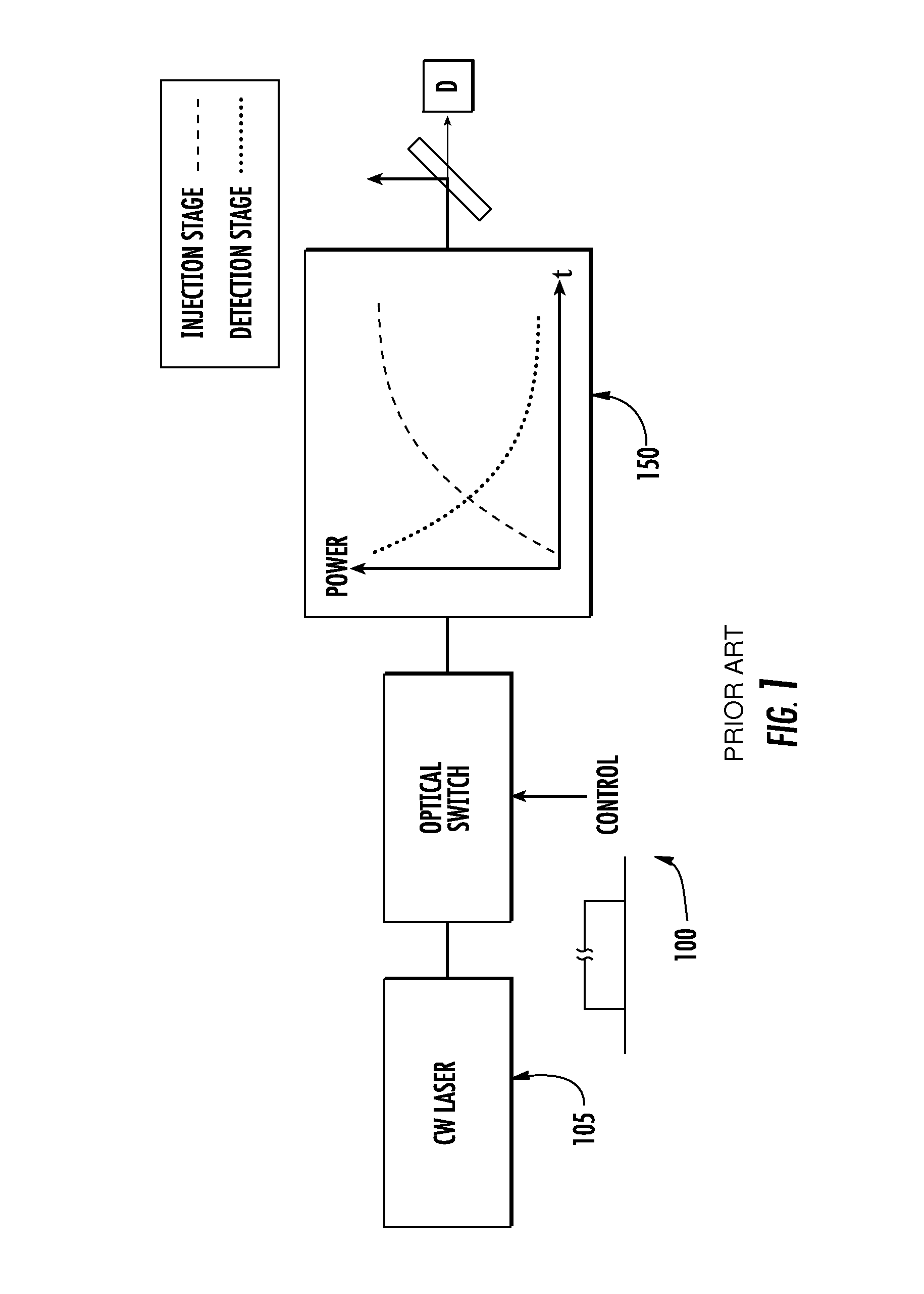
[0027]A conventional cavity ring down spectrometer configuration 100 is further depicted in FIG. 1. Generally, a cw laser output is injected into the ring down cavity, leading to a buildup of the optical power, referred to herein as intra-cavity signal evolution within the ring down cavity. FIG. 1 schematically illustrates such an arrangement having cw laser 105 and ring down cavity 150, with an optical switch disposed therebetween. In at least one embodiment the optical switch controls transmission. The optical switch may include an acousto-optic or electro-optic device in either bulk or integrated form. Cw laser injection can be controllably interrupted with the optical switch. When the optical switch is controlled to allow transmission (e.g.: closed with a TTL control signal), the cw beam is injected into the ring cavity, with intra-cavity signal evolution illustrated with the buildup of power in ring-down cavity 150. When the switch prevents transmission, the diminishing intra-c...


PUM

PropertyMeasurementUnit
frequencyaaaaaaaaaa
frequencyaaaaaaaaaa
frequencyaaaaaaaaaa

Abstract

The present invention relates to precision linewidth control and frequency measurements of continuous wave lasers for the near to far IR spectral regions, precision frequency synthesizers and exemplary applications in molecular detection. Methods and systems are disclosed for simultaneous line narrowing of cw lasers, as well as referencing the desired emission wavelength to a frequency comb laser.

Description

FIELD OF THE INVENTION[0001]The present invention relates to precision linewidth control and frequency measurements of continuous wave lasers for the near to far IR spectral regions, precision frequency synthesizers and exemplary applications in molecular detection.BACKGROUND[0002]Tunable continuous wave (cw) lasers are essential tools for precision spectroscopy applications such as trace gas detection and frequency measurements. Trace gas detection is particularly sensitive when coupling the cw lasers into a high finesse gas-filled external enhancement cavity which greatly increases the interaction length of the trace gases with the cw light. Because many commercially available cw laser sources, particularly quantum cascade lasers, have relatively large emission linewidths, they cannot be efficiently coupled into high finesse enhancement cavities, which can have acceptance bandwidths as low as 10 kHz, or even lower.[0003]Generally this requirement is resolved by electronic or optic...

Claims


Application Information

Patent Timeline
Patent Type & Authority Patents(United States)
IPC IPC(8): G01J3/45G01N21/3504H01S3/13G01J3/10G02F1/35G01N33/00H01S3/00H01S5/0687
CPCG01N33/0027G01N21/3504G01J3/108H01S3/0092H01S5/0687H01S5/4025G01J3/10G01J9/04G02F1/3534G02F1/353H01S5/0092H01S5/0657H01S5/06821H01S5/06832G01N2201/06113
Inventor FERMANN, MARTIN E.MARANGONI, MARCOGATTI, DAVIDE
Owner IMRA AMERICA
Why Eureka
Try Eureka