LADAR enabled impact mitigation system
a technology of impact mitigation and laser, applied in the direction of pedestrian/occupant safety arrangement, suspension, instruments, etc., can solve the problems of unavoidable crash, automobile occupants exposed to road hazards, and other vehicle dangers, so as to reduce the severity of the impact, lessen the damage caused by the impact, and mitigate the effect of the impa
- Summary
- Abstract
- Description
- Claims
- Application Information
AI Technical Summary
Benefits of technology
Problems solved by technology
Method used
Image
Examples
first embodiment
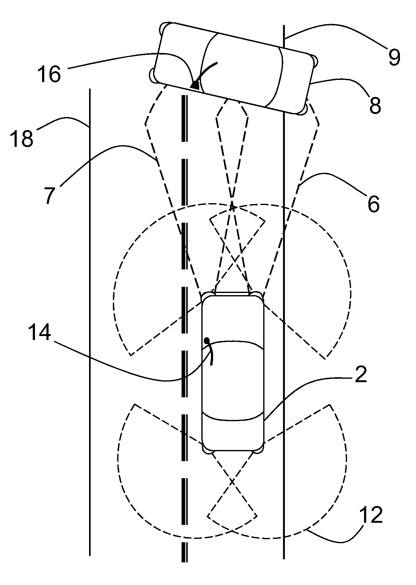
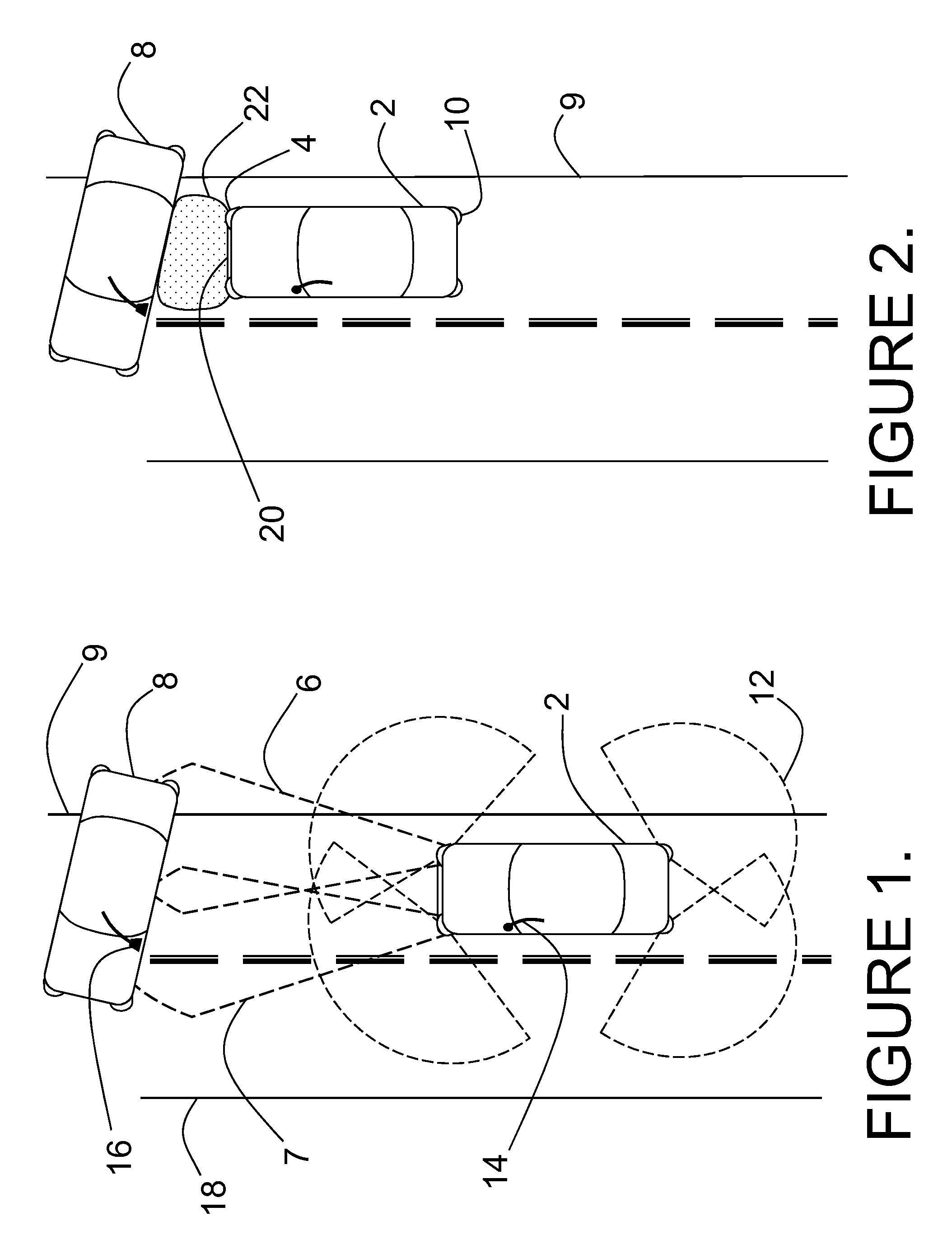
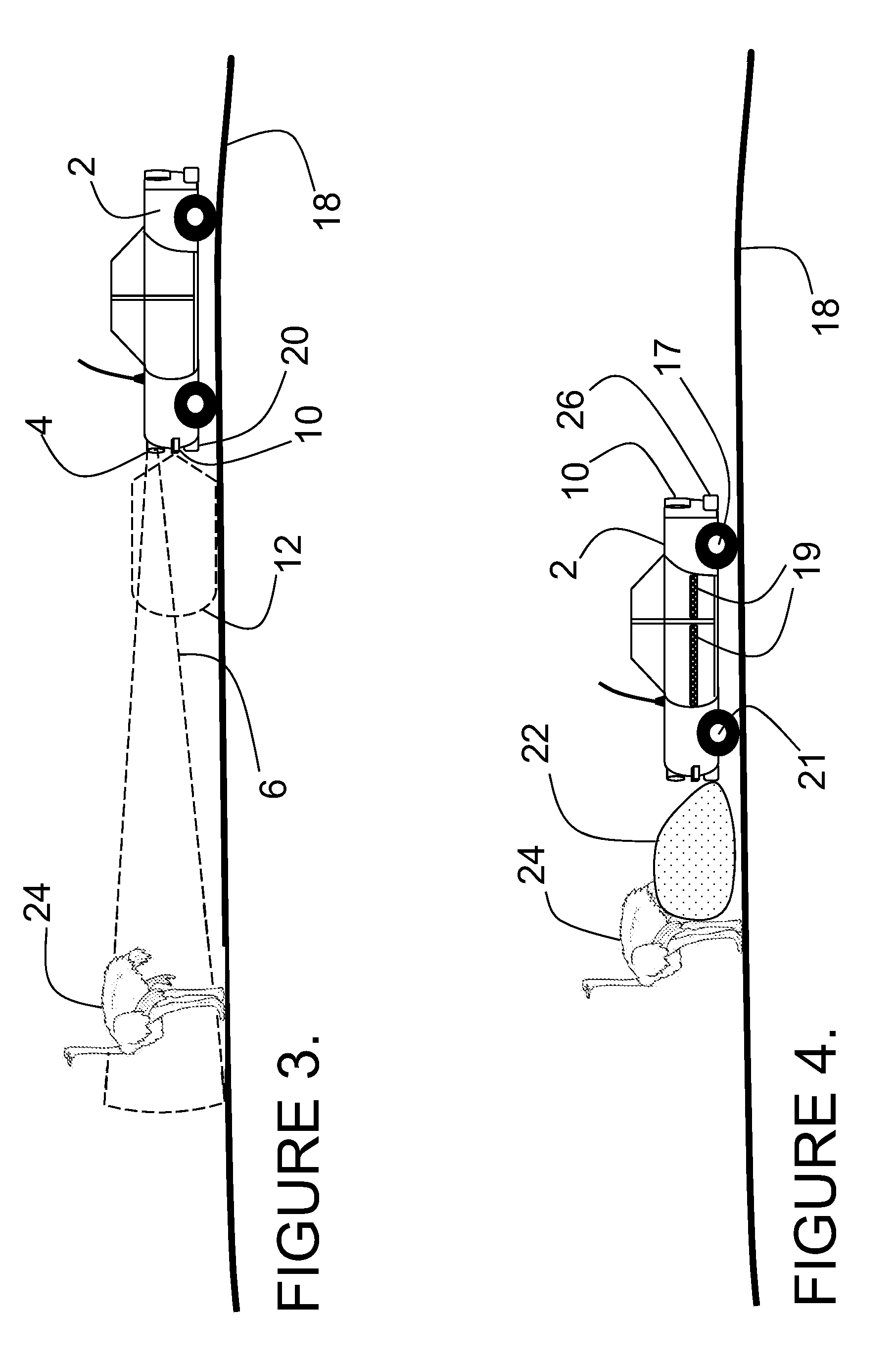
[0032]FIG. 1 depicts the impact mitigation system installed on a first vehicle 2 involved in a collision threat scenario with a second vehicle 8, which is spunout and stationary in the roadway ahead. The forward radiation pattern 6 of a long range ladar sensor embedded in a headlight assembly of first vehicle 2 is shown by dashed lines where it intersects with the driver's side of second vehicle 8, which is positioned laterally across the lane and the right edge of the roadway 9. Second vehicle 8 obstructs part of the second lane of traffic, but does not extend over the left edge of the roadway 18. A second forward radiation pattern 7 from a second long range ladar sensor embedded in a second headlight assembly is shown overlapping first radiation pattern 6. The radiation pattern 12 of a short range ladar sensor embedded in an auxiliary lamp assembly is shown projecting radially from a corner of first vehicle 2 and also at the other three corners of first vehicle 2. First vehicle 2 ...
second embodiment
[0043]FIG. 11 shows a variable ride suspension system with a coil spring 70 providing the nominal ride height for the vehicle. Coil spring 70 mounts coaxially over the outside diameter of cylinder 54 of active suspension component 61. The tire 78, rim 76, and wheel 74 are partially cut away to give a better view of the upright 68 and hub 72. Lower spring cup 75 is rigidly attached to piston 52 of active suspension component 61 and engages with the bottom end of coil spring 70. Upper spring cup 73 engages with the top of coil spring 70 and rests securely against the fender (not shown) of the vehicle indicated by dashed line 77. Fitting 62 is repositioned to be accessible through the fender of the vehicle, and umbilical 60 connects to the vehicle electrical, pneumatic, and / or hydraulic systems. FIG. 11 does not show any of the vehicle steering linkages in the interests of clarity.
[0044]FIG. 12 shows a road hazard scenario involving first vehicle 2 and a dip 82 in the roadway 18, a pot...
third embodiment
[0045]In FIG. 13, the onboard suspension control system, knowing the depth and shape of the dip 82, and the spring rate of the coil spring or compressed air bearing the vehicle load, may simply allow the suspension to passively track through the dip 82. For some types of dips 82, and some suspension characteristics, this may be an optimum solution for the stability and control of the vehicle 2. In the case of a deep dip 82, or a soft sprung vehicle suspension, it may be necessary to actively drive the left front wheel 21 lower by using an electrical impulse into an active suspension component 61 as described in association with FIGS. 10 & 11. In an alternative embodiment, hydraulic fluid under pressure may be applied to active suspension component 61, and used to drive the left front wheel 21 lower into the dip 82. In a third embodiment, an impulse of compressed air is applied to an active suspension component 61 in order to drive the left front wheel 21 lower into the dip 82 in ord...
PUM
 Abstract
Description
Claims
Application Information
 - R&D
- Intellectual Property
- Life Sciences
- Materials
- Tech Scout
- Unparalleled Data Quality
- Higher Quality Content
- 60% Fewer Hallucinations
Browse by: Latest US Patents, China's latest patents, Technical Efficacy Thesaurus, Application Domain, Technology Topic, Popular Technical Reports.
© 2025 PatSnap. All rights reserved.Legal|Privacy policy|Modern Slavery Act Transparency Statement|Sitemap|About US| Contact US: help@patsnap.com


