
Low profile rod pumping unit with pneumatic counterbalance for the active control of the rod string

a low-profile, rod-string active control technology, applied in the direction of gearing, positive-displacement liquid engine, borehole/well accessories, etc., can solve the problem of inefficient utilization of the capacity of these driveline elements, interference of waves from multiple sources along the rod string, and large interaction of counterbalance torque produced by one of the various methods abov

Active Publication Date: 2015-08-25
RAVDOS HLDG INC
View PDF16 Cites 6 Cited by
  • Summary
  • Abstract
  • Description
  • Claims
  • Application Information

AI Technical Summary

Benefits of technology

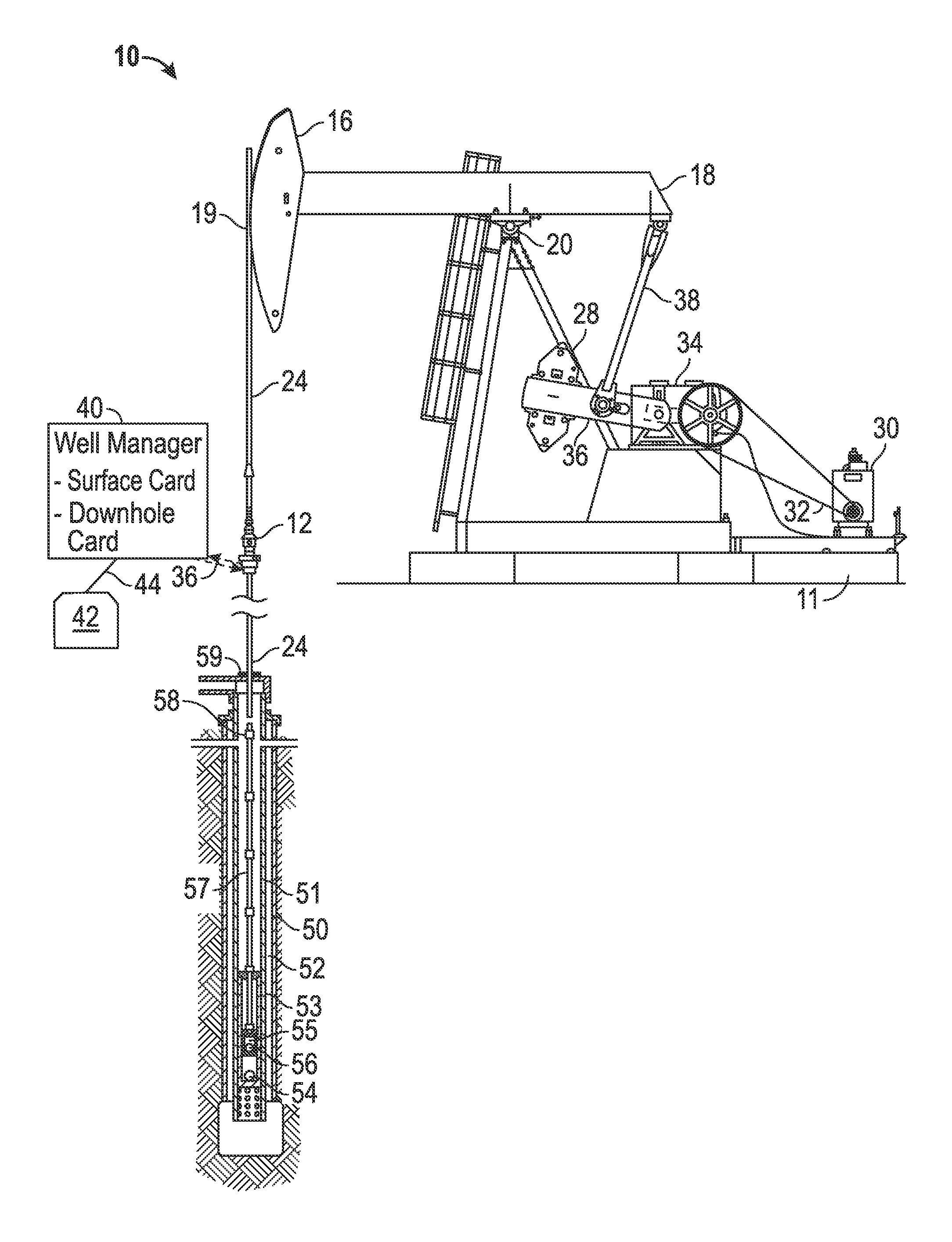
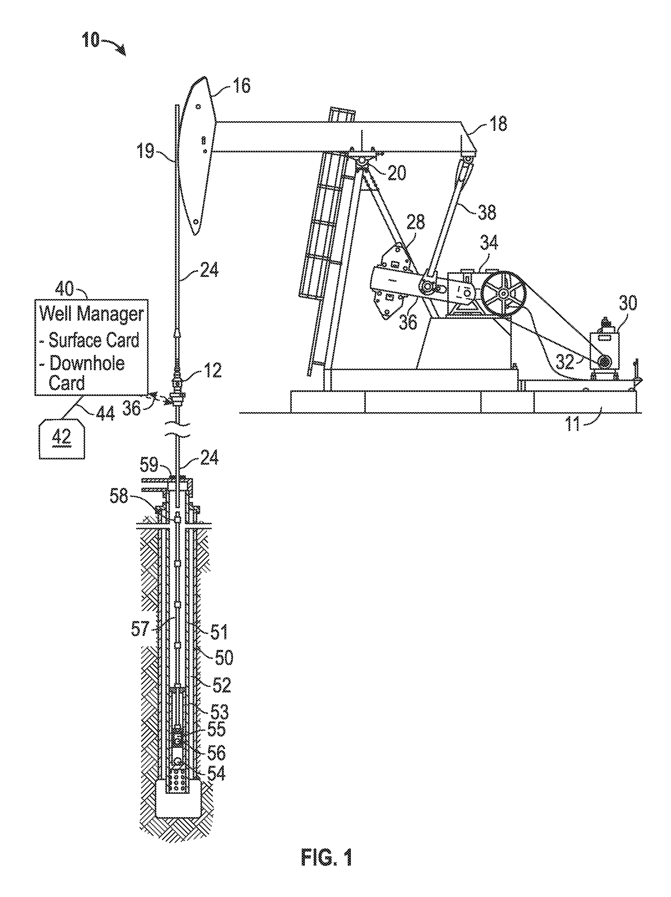
[0026]In accordance with select aspects of the disclosure, an adaptable surface pumping unit that combines automation technology with a low-inertia pumping unit mechanism capable of responding to active control commands from well management automation system, thereby adapting to changing well conditions. Such a pumping unit is capable of self-optimization, self-production, and of safeguarding expensive down-hole equipment. Additionally, such a pumping unit has a small environmental footprint in that it is designed in such a way that safety hazards are eliminated or reduced to the point that guarding and warning signage requirements are minimal.
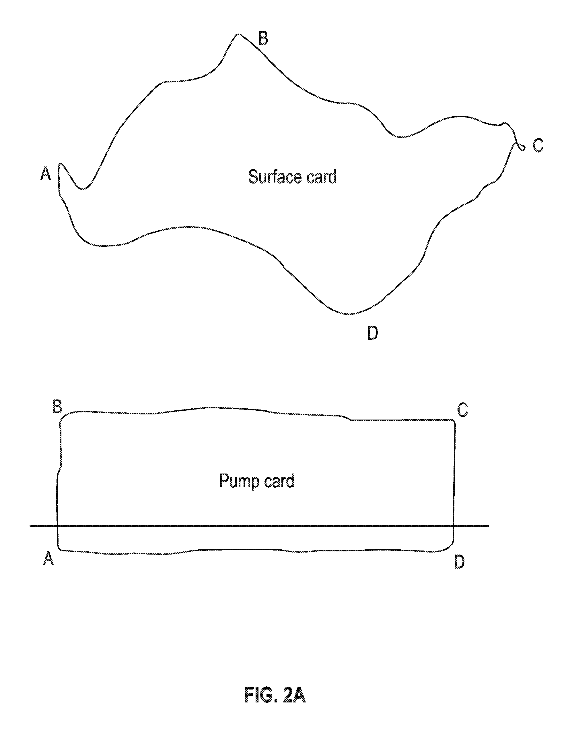
[0031]In yet another aspect of the present disclosure, a system and method for actively controlling the motion of a rod pumping unit to improve fluid production volume by incrementally increasing work performed within the pumping cycle, wherein the method includes analyzing well dynamometer data, comparing the dynamometer data to one or more pumping unit permissible load envelopes, and varying pumping speed of the rod pumping unit through regions of the dynamometer to reduce load and torque where needed, and / or expand the vertical load range in the dynamometer card through under-utilized sections of the permissible loading envelope to maximize cycle work (production), thereby protecting the rod string from the onset of conditions such as buckling or excessive stress levels.

Problems solved by technology

Simultaneously, the counterbalance torque produced by one of the various methods above interacts with the well load torque negating a large percentage of it.
Magnitude and phase angle mismatches between well and counterbalance torque curves are the source of “lumpiness” in the net torque transmitted through the gear reducer and up-stream driveline elements.
it is evident that the “lumpiness” in the net torque curve results in inefficient utilization of the capacity of these driveline elements.
Traveling stress waves from multiple sources interfere with each other along the rod string (some constructively, others destructively) as they traverse its length and reflect load variations back to the surface pumping unit where they can be measured and graphed as part of the surface dynamometer card.
These preferences are fundamental to a particular linkage geometry and are very difficult to change.
The extra available work capacity of the Mark II pumping unit would be underutilized in this particular application.
An unfortunate reality is that rod pumping dynamometer cards are almost never the vaguely hourglass shape that would maximize the work potential of most beam pumping units, at least not under the near constant rotating velocity conditions under which they have been designed to operate.
Unfortunately, the flywheel effect produced by massive rotating components within the pumping unit resists rapid changes in speed.
Cranks, counterweights, gears, sheaves, brake drums and other rotating components in the system contribute to the overall flywheel effect and require significant torque exertion to alter their rotating speed.
This presents a substantial impediment to active control scenarios such as those mentioned above.
Attempts to substantially alter speed within the pumping cycle with a VSD to date have generally consumed disproportionately more power which negatively affects operating cost.
Mass based counterbalance systems present problems in continually maintaining optimum counterbalance as well conditions change.
Fluid level in the casing annulus of the well tends to decline with production over time.
As fluid level drops, the rod pumping system must lift the fluid from greater depth increasing the amount of counterbalance needed.
Failure to maintain proper counterbalance can lead at best to inefficient power usage and at worst to upstream equipment failures due to overload.
Generally, counterbalance adjustments on existing beam unit designs are performed manually by repositioning, adding or removing counterweights in an equipment and labor intensive process requiring unit shut-down and restraint, entry into a hazardous area, use of expensive cranes and equipment, and temporary loss of production to the operator.

Method used


Image

  • Low profile rod pumping unit with pneumatic counterbalance for the active control of the rod string
  • Low profile rod pumping unit with pneumatic counterbalance for the active control of the rod string
  • Low profile rod pumping unit with pneumatic counterbalance for the active control of the rod string

Examples


Embodiment Construction

[0055]The Figures described above and the written description of specific structures and functions below are not presented to limit the scope of what Applicants have invented or the scope of the appended claims. Rather, the Figures and written description are provided to teach any person skilled in the art to make and use the inventions for which patent protection is sought. Those skilled in the art will appreciate that not all features of a commercial embodiment of the inventions are described or shown for the sake of clarity and understanding. Persons of skill in this art will also appreciate that the development of an actual commercial embodiment incorporating aspects of the present inventions will require numerous implementation-specific decisions to achieve the developer's ultimate goal for the commercial embodiment. Such implementation-specific decisions may include, and likely are not limited to, compliance with system-related, business-related, government-related and other c...


PUM


Abstract

Adaptable systems for a surface pumping unit that includes a low inertia pumping unit mechanism having a pneumatic counterbalance assembly are described, as well as methods for the use of such systems for subterranean fluid recovery. The system is capable of being integrated with well management automation systems, thereby allowing for response to active control commands, and automatically altering and / or maintaining a counterbalance force in the pumping unit by adding or removing air mass from a containment vessel associated with the pumping unit.

Description

CROSS REFERENCE TO RELATED APPLICATIONS[0001]This applications claims priority to U.S. Provisional patent application Ser. No. 61 / 557,269, filed Nov. 8, 2011, the contents of which are incorporated herein by reference in their entirety.STATEMENT REGARDING FEDERALLY SPONSORED RESEARCH OR DEVELOPMENT[0002]Not applicable.REFERENCE TO APPENDIX[0003]Not applicable.BACKGROUND OF THE INVENTION[0004]1. Field of the Invention[0005]The inventions disclosed and taught herein relate generally to mechanical counterbalances, and more specifically are related to pneumatic counterbalances suitable for use in machinery, such as linear rod pumping units.[0006]2. Description of the Related Art[0007]Beam pumping units and their upstream drive components are exposed to a wide range of loading conditions. These vary by well application, the type and proportions of the pumping unit's linkage mechanism, and counterbalance matching. The primary function of the pumping unit is to convert rotating motion from...

Claims


Application Information

Patent Timeline
Patent Type & Authority Patents(United States)
IPC IPC(8): E21B43/12F04B47/02F04B47/04
CPCE21B43/127E21B43/12F04B47/02F04B47/04Y10T74/18182F04B47/14
Inventor DOYLE, DAVID W.
Owner RAVDOS HLDG INC
Learn More