Capacity control valve
a technology of capacitive control valve and valve body, which is applied in the direction of valve operating means/release devices, machines/engines, positive displacement liquid engines, etc., can solve the problems of adversely affecting the control speed of the swash plate, the inability to change the seal diameter d ultimately, and the inability to manufacture and urging the urging means, etc., to achieve efficient utilization, facilitate the manufacture and urging force setting of the urging means, and increase the pitch of the coil
- Summary
- Abstract
- Description
- Claims
- Application Information
AI Technical Summary
Benefits of technology
Problems solved by technology
Method used
Image
Examples
first embodiment
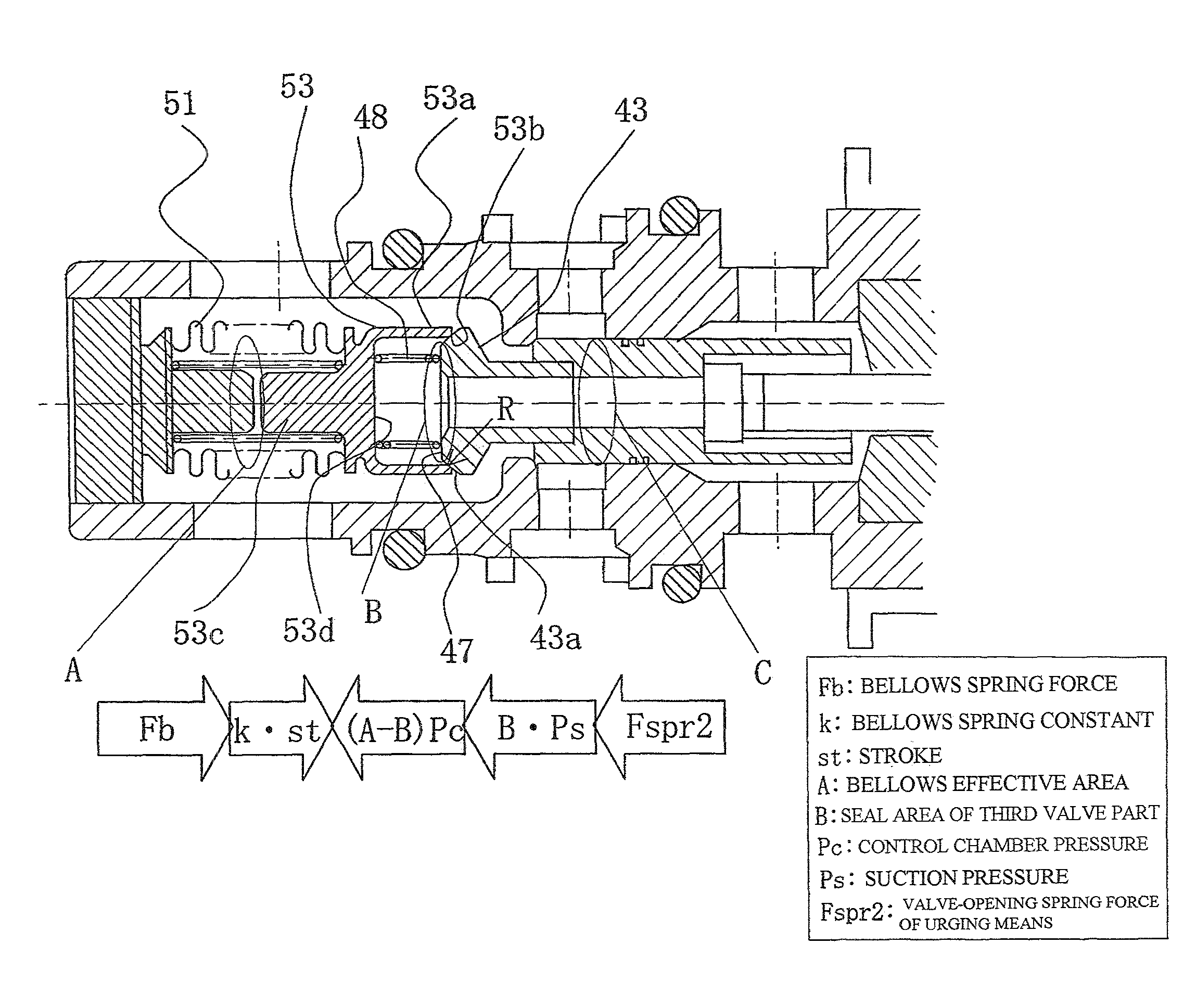
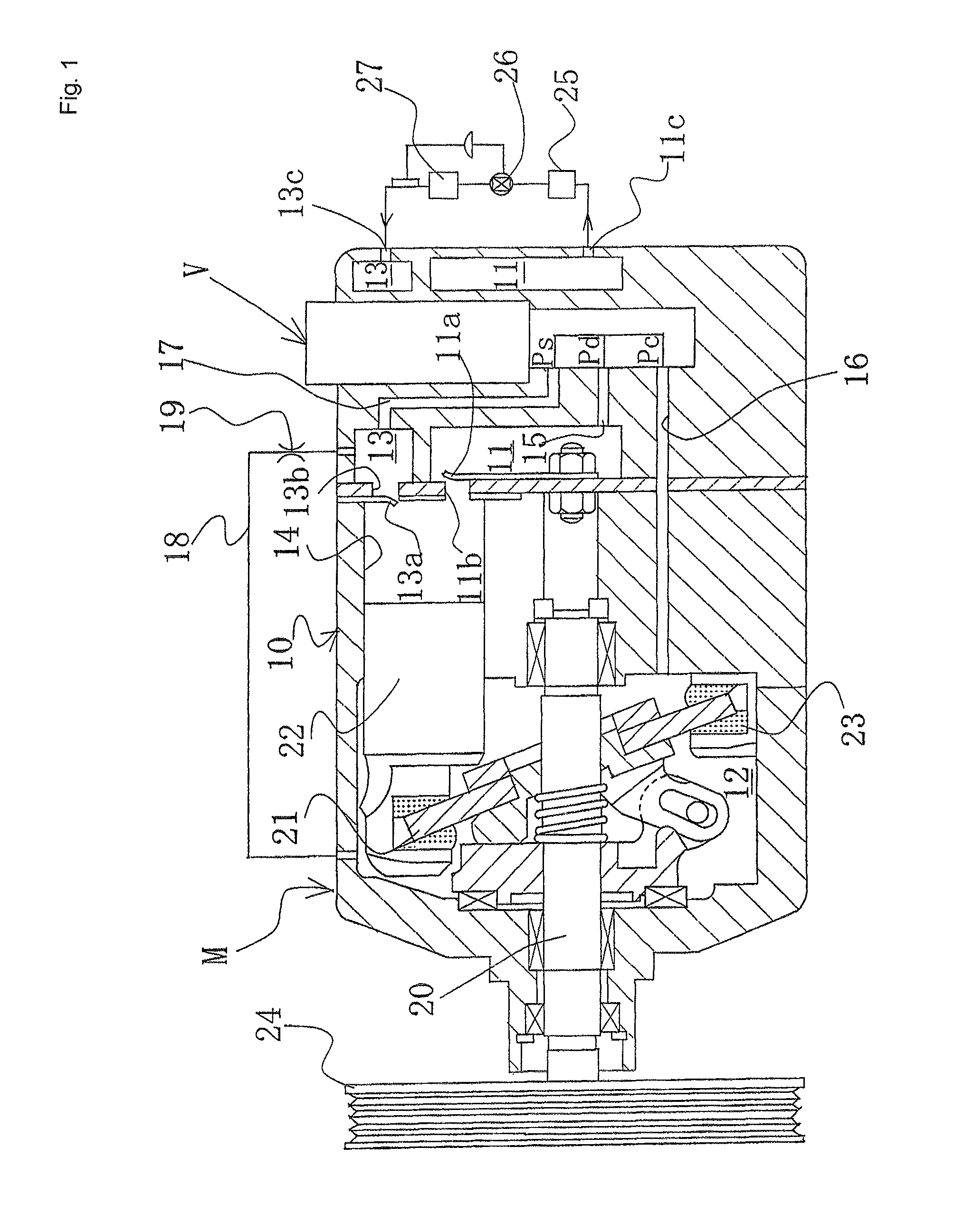
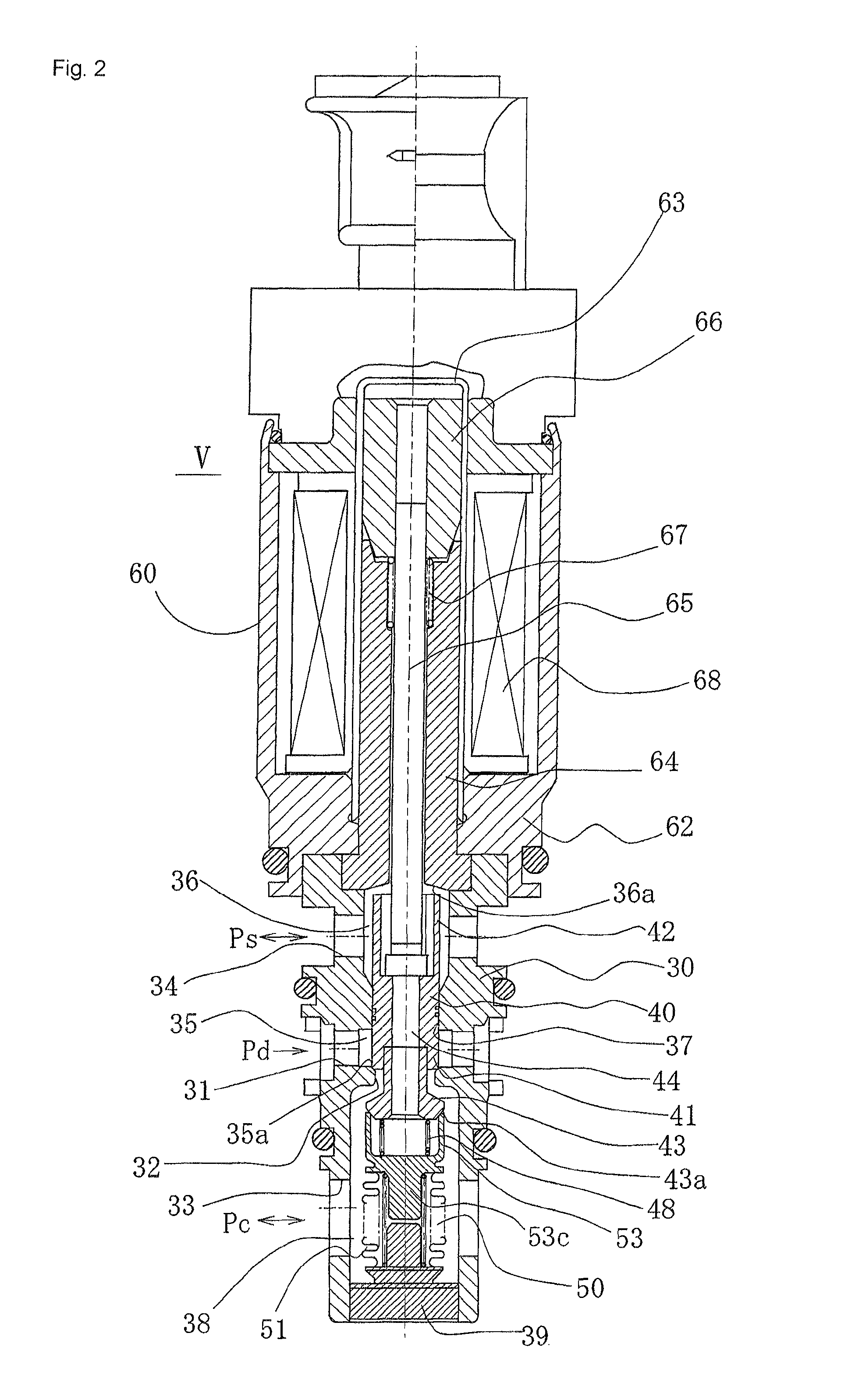
[0059]As shown in FIG. 1, a swash plate variable-capacity compressor M is provided with a discharge chamber 11, a control chamber (also referred to as a crankcase) 12, a suction chamber 13, a plurality of cylinders 14, a port 11b communicating the cylinders 14 and the discharge chamber 11 and opened and closed by a discharge valve 11a, a port 13b communicating the cylinders 14 and the suction chamber 13 and opened and closed by a suction valve 13a, a discharge port 11c and suction port 13c connected to an external refrigerant circuit, a communicating passage 15 as a discharge-side passage for communicating the discharge chamber 11 and the control chamber 12, a communicating passage 16 which serves both as the aforementioned discharge-side passage and as a suction-side passage for communicating the control chamber 12 and the suction chamber 13, a casing 10 for demarcating a communicating passage 17 as a suction-side passage and other components, a rotating shaft 20 protruding outward...
second embodiment
[0109]FIG. 5 is a sectional front view showing a second embodiment of the capacity control valve of the present invention.
[0110]In FIG. 5, reference numerals that are the same as those in FIG. 2 refer to the same members, and no detailed description of such members is given hereinafter.
[0111]In the second embodiment, a flange 45 extending through the entire circumference is provided on an outside surface positioned closer to the solenoid 60 than the end surface 47 of the third valve part 43, and a flange 54 extending through the entire circumference is also provided in the adapter 53 on a basal outside surface of the hollow cylindrical part 53a. The urging means 48 is installed between the flange 45 of the third valve part 43 and the flange 54 of the adapter 53, along the external periphery of the hollow cylindrical part 53a of the adapter 53, and acts in the valve-opening direction of the third valve part 43 and the adapter 53. The urging means 48 comprises a coil spring or other s...
PUM
 Abstract
Description
Claims
Application Information
 - R&D
- Intellectual Property
- Life Sciences
- Materials
- Tech Scout
- Unparalleled Data Quality
- Higher Quality Content
- 60% Fewer Hallucinations
Browse by: Latest US Patents, China's latest patents, Technical Efficacy Thesaurus, Application Domain, Technology Topic, Popular Technical Reports.
© 2025 PatSnap. All rights reserved.Legal|Privacy policy|Modern Slavery Act Transparency Statement|Sitemap|About US| Contact US: help@patsnap.com


