
Apparatus and method for continuous powder coating

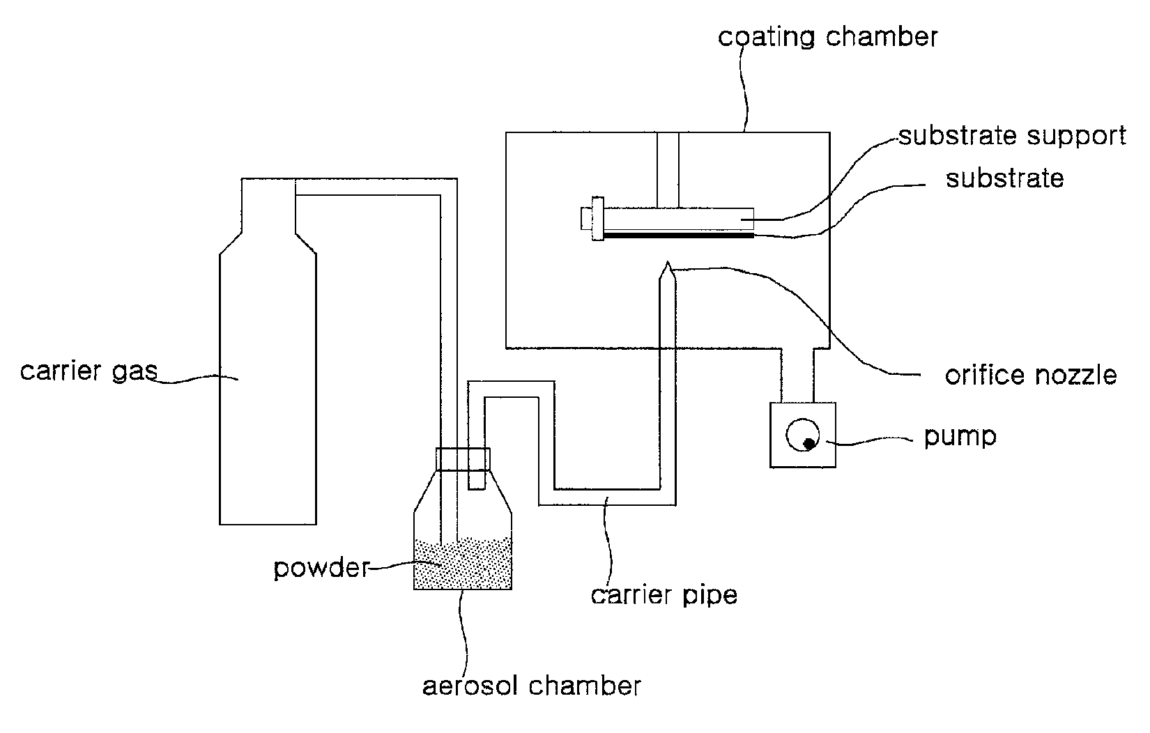
a technology of apparatus and coating layer, applied in the direction of liquid spraying apparatus, coating, pressure inorganic powder coating, etc., can solve the problems of deteriorating chemical properties of powder, weakening the adhesion strength between the substrate and the coated layer, and difficult to control the thickness of the coated layer

Active Publication Date: 2015-09-22
FEMVIX +2
View PDF18 Cites 3 Cited by
  • Summary
  • Abstract
  • Description
  • Claims
  • Application Information

AI Technical Summary

Benefits of technology

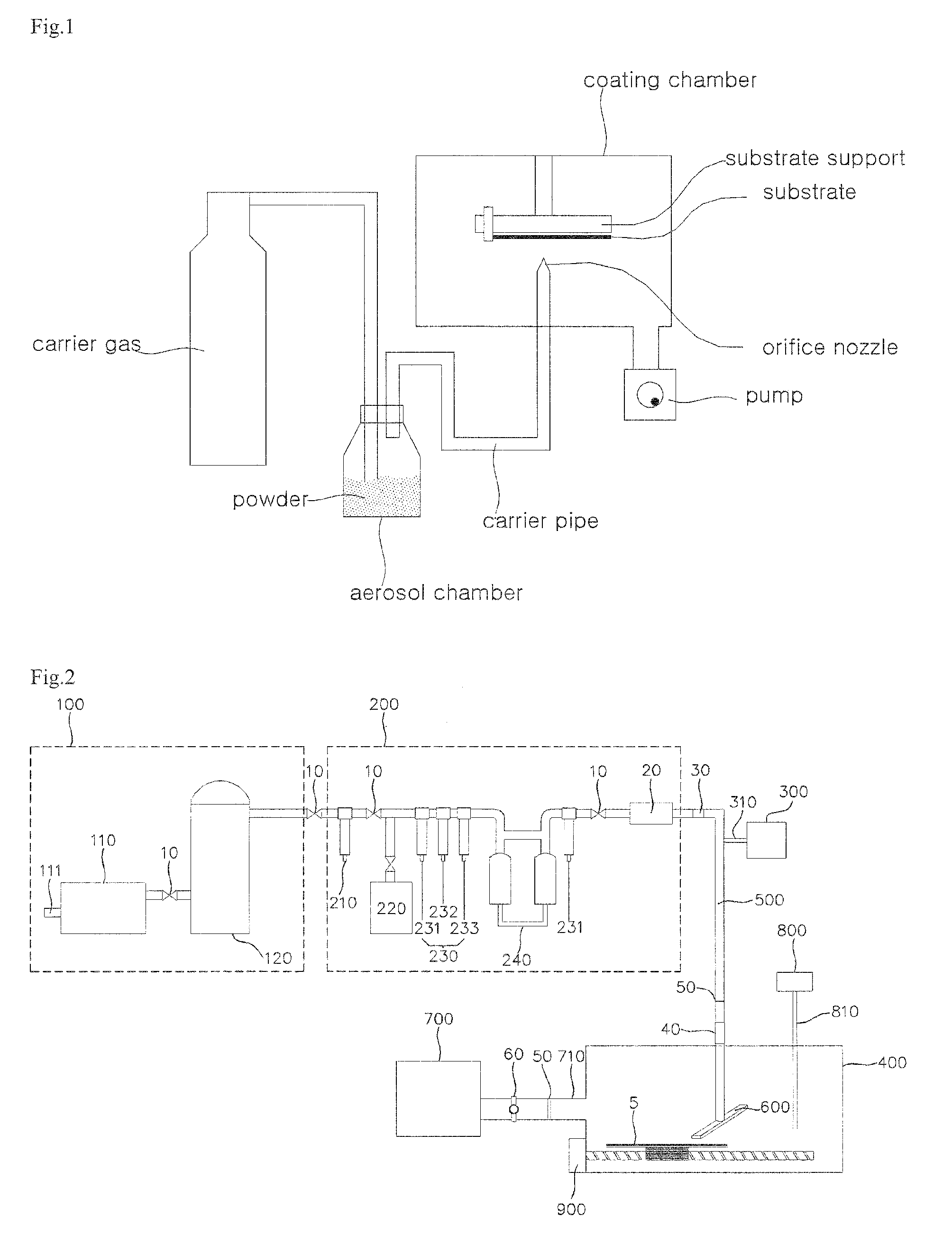
The present invention is about a device used to apply powder to a substrate. The device includes a vacuum connection pipe and a pressure control valve to keep and adjust the vacuum inside the coating chamber where the substrate is located. A substrate transporter is installed inside the coating chamber to move the substrate back and forth and the velocity of the substrate transporter can be controlled based on the pressure of the carrier pipe and the coating chamber. As a result, the device controls the flow rate of the carrier air, pressure in the coating chamber, and powder feeding and spraying, which ensures even distribution of powder in the carrier air and consistent concentration. This results in a uniform thin layer of powder on the substrate.

Problems solved by technology

Thermal spraying can make a thick coating layer in a short time, but this coating process using the high temperature results in several problems such as containing voids and cracks inside the coated layer, deteriorating chemical property of the powder, shaping amorphous phase, weakening the adhesion strength between the substrate and the coated layer due to the high temperature and rapid cooling time.
Besides, the surface of the layer is rough and it is hard to control thickness of the coated layer.
Deficiency of this technique is that the particles being charged electrically such as carbon or metal powder can be only coated, but the ceramic particles cannot.
The weakness of cold spray is that particles are not coated because their velocity decreases by the aerodynamic drag occurring after gas impinges upon the substrate.
But as mentioned above, its deficiency is that there is difficulty coating a substrate with powder because of the aerodynamic drag.
And the technique has a problem depositing ceramic powder since it is not deformed plastically, unlike metal powder.
Accordingly, the efficiency of coating declines considerably even if coating is possible.
But it also failed to overcome the problems shown from cold spray.
But it was not successful since it was not possible to make a thin layer with uniformity and low sheet resistance by the aerosol deposition technique.
These properties of the carbon nanotubes have been the obstacle to manufacturing commercialized large size products which absolutely need uniform coating.
But there is a problem coating continuously and uniformly because when adjusting the pressure to get necessary pressure, velocity of powder changes which means that there is difficulty getting a uniform coating layer.
The aerosol chamber has a filter or a windmill to disperse the entangled powder, but it could produce the opposite effect on dispersion and the filter could make the flow rate of carrier gas worse.
It results in unsteady feeding of powder and being not able to form a uniform coating layer.
But it has no effect on dispersing the powder such as carbon nanotubes and cannot solve the problem of uniformity when coating a large size substrate.
Furthermore, there is another problem generating high heat because of high sheet resistance of the unevenly coated substrate when transmitting an electrical current.
In the technique disclosed in Korea Pat. No. 10-0724070 (“Composite structured material and method for preparation thereof and apparatus for preparation thereof”; PCT / JP2000 / 007076), microwave or supersonic wave was beamed on aerosol to make particles dispersed smoothly and uniformly, but its effect on dispersion was not satisfactory, especially in the case of carbon nanotube powder.
But it is very hard to make a uniform thin layer by a conventional aerosol deposition because of a problem controlling the amount of the transported aerosol.
It is a serious problem of the aerosol deposition.
Another weakness of the aerosol deposition is keeping the deposition chamber at a high vacuumed state to get the powder deposited well by raising the velocity of aerosol which means that it takes a long time to prepare for coating.
But the method has a problem transporting a fixed amount of powder continuously which must be solved for a good quality of coating.
A problem of this method is that much of powder near the low part of the reservoir is pushed up although some powder goes down to the manifold and then to a nozzle.
In the process of feeding there is a problem that powder contained in a feeder is under atmospheric pressure and therefore it cannot be flowed into a nozzle unit when a compressed gas flows into the feeder.
In the above-described 5)˜6) patents, powder in a hopper under atmospheric pressure is discharged by self weight without using a device and therefore it is not possible to control an amount of discharged powder which means that thickness and quality of a coating layer cannot be consistently kept by the feeding method.
As described above, there are several problems that must be improved in the method feeding powder into a pressure pipe having higher pressure than atmospheric pressure.
1) Need of high pressure (10˜40 bar) more than atmospheric pressure 2) Use of costly nitrogen gas or helium gas to obtain high pressure 3) Backflow or tie-up of the powder flow when gas of higher pressure than atmospheric pressure flows into a feeder under atmospheric pressure 4) Difficulty in feeding a little and consistent amount of powder.

Method used


Image

  • Apparatus and method for continuous powder coating
  • Apparatus and method for continuous powder coating
  • Apparatus and method for continuous powder coating

Examples


first embodiment

2. First Embodiment

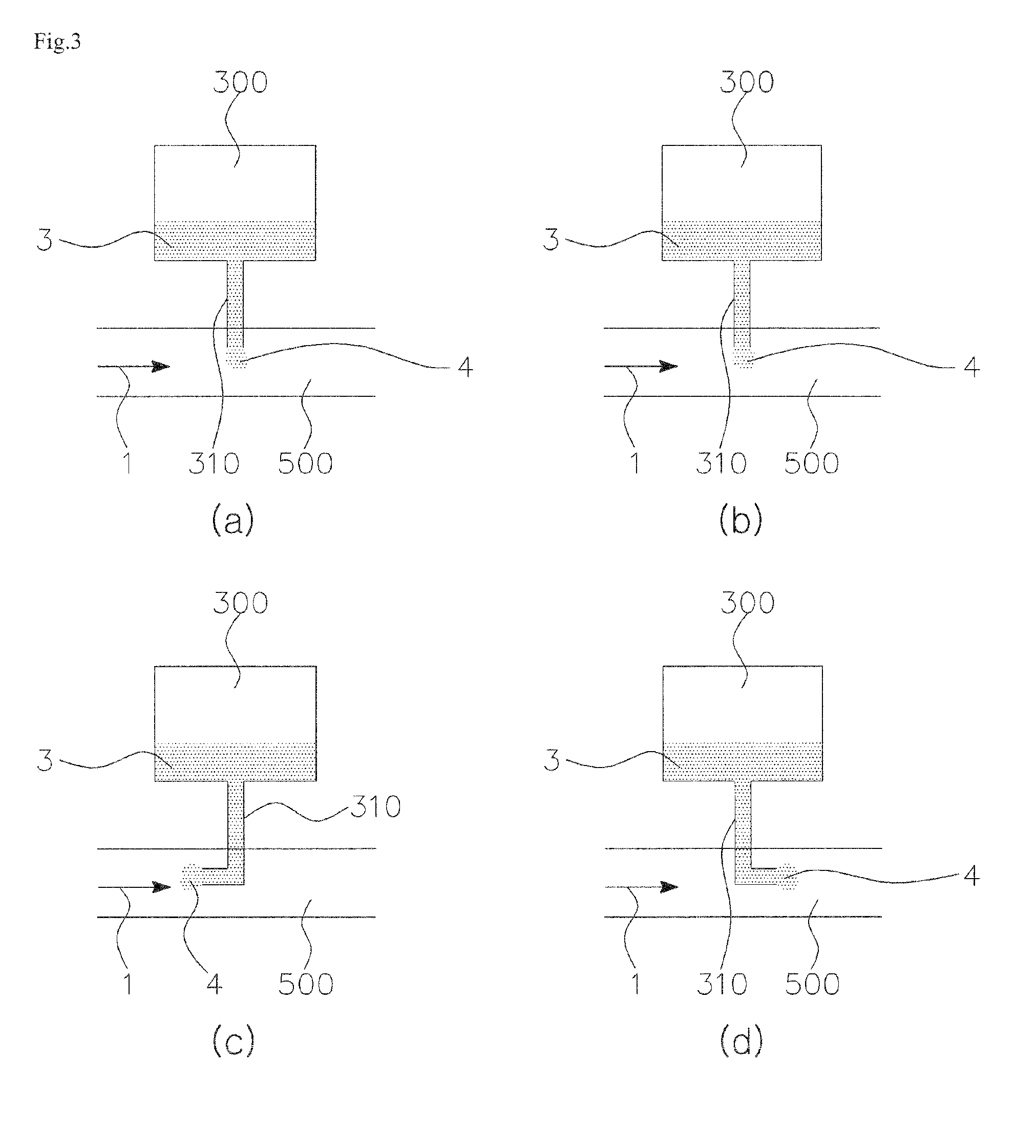
[0238]As shown in [FIG. 7], the carrier pipe of the first embodiment is divided into the five sections such as a first section, a second section, a third section, a fourth section, and a fifth section. A pipe diameter of the first section, the third, and the fifth does not change, but the second and the fourth have a throat in the middle of a pipe and so a pipe diameter gradually scales down moving toward the throat from the ends of each section. The throat of the fourth section is bigger than it of the second section. The third section is connected to the feeder (300) by a connection pipe (310) and a block chamber (330) which has an open side (320) on its top.

[0239]As shown in [FIG. 6], powder at atmospheric pressure (P4) is fed into said carrier pipe (500) containing carrier air higher than atmospheric pressure (P1, P1′) as forming a specific section at minus pressure (P3) in the carrier pipe. For this feeding, the cross-sectional area of the carrier pipe in the...

second embodiment

3. Second Embodiment

[0274]The present invention provides an apparatus for powder feeding. It is composed of a spray nozzle that is connected to the end of the carrier pipe, one or several feeders that are connected to the second section of the carrier pipe through the powder pipe and have an open side on them, and the carrier pipe which consists of the first section that the diameter of the carrier pipe is uniform up to one point and converges at a certain ratio, the second section that the diameter of the pipe is uniform up to one point and then diverges at a certain ratio, and the third section that has the uniform diameter of the pipe.

[0275]In the present invention, powder (3) at atmospheric pressure is fed into the carrier pipe (500) as the minus pressure space is formed in the carrier pipe (500) as shown in [FIG. 13]. The carrier pipe, therefore, is divided into from the first section to the third section.

[0276]The first section is divided into two parts. The diameter of one pa...


PUM

PropertyMeasurementUnit
pressureaaaaaaaaaa
particle sizesaaaaaaaaaa
pressureaaaaaaaaaa

Abstract

The present invention relates to a method and an apparatus by which powder is evenly dispersed and is coated on a substrate uniformly and continuously so that a uniform layer may be formed. More specifically the present invention provides a method and an apparatus for forming a coating layer that powder is coated on an entire surface of a substrate uniformly and continuously, regardless of the material or the size of the substrate, as a uniform amount of powder entrained on the carrier air which is generated by carrier air and powder transported to a carrier pipe at a certain rate is consistently fed in to a nozzle, regardless of the size, morphology, and specific weight of the powder particles.

Description

FIELD OF THE INVENTION[0001]The present invention relates to a method and an apparatus that coat solid powder on the substrates such as plastics, glasses, alloys, metals, ceramics, etc. continuously and uniformly by spraying powder entrained on carrier air regardless of the size, morphology, and specific weight of the powder.DESCRIPTION OF THE PRIOR ARTS[0002]The conventional coatings spraying the powder on a substrate have been affected by the size, the specific weight, heat treatment of the powder and temperature of the substrate (high temperature, low temperature, or room temperature), degree of vacuum, and velocity of the sprayed particles, etc. And all of these factors have a vital effect on productivity and economics of the coating. The powder refers to the solid powder of plastics, glasses, alloys, metals, semimetals, ceramics, and composites.Conventional Coatings[0003]1) Thermal Spraying[0004]Generally, thermal spraying coats a surface with the powder melted by plasma, arc, ...

Claims


Application Information

Patent Timeline
Patent Type & Authority Patents(United States)
IPC IPC(8): B05D1/12B05B7/14C23C24/04
CPCC23C24/04B05B7/144B05B7/1454
Inventor KIM, OK RYULKIM, OK MINLEE, KUEN SIKCHEONG, SEUNG CHAE
Owner FEMVIX
Learn More