Electromagnetic propulsive motor

a propulsive motor and electromagnetic technology, applied in the direction of synchronous motors, magnetic circuit rotating parts, magnetic circuit shapes/forms/construction, etc., can solve the problems of high operating cost, undesirable pollutants produced as a byproduct of jet fuel combustion, and large thrust of known gas turbine engines

Active Publication Date: 2015-09-22
USKERT RICHARD CHRISTOPHER
View PDF8 Cites 47 Cited by
  • Summary
  • Abstract
  • Description
  • Claims
  • Application Information

AI Technical Summary

Benefits of technology

[0010]The principles and concepts embodied in the present invention may also be employed with a turbofan engine, for example a bypass fan motor configuration. Furthermore, the rotor / stator electromagnetic element interaction can be utilized as a generator of electrical power where the rotor is spinning freely and is not required to be driven.

Problems solved by technology

Known gas turbine engines produce large amounts of thrust but are typically costly to operate and manufacture due to the necessity to burn large quantities of jet fuel to drive the turbine.
Additionally, the pollutants produced as a byproduct of jet fuel combustion are undesirable.
Since the gas passing through the engine aft of the combustor is quite hot, all engine components are subjected to tremendous heat.
Furthermore, the rotating components of a gas turbine engine have very high rotational velocities, that, when coupled with thermal expansion and impacts caused by normal engine operation cause them to rub or interfere with the static portions of the turbine.
These inherent features of modern gas turbines render them quite costly to produce, as all components must be produced to extremely tight tolerances and be capable of withstanding enormous thermal and mechanical stresses.
Additionally, many prior art rotor and stator assemblies are quite complex, having a multiplicity of parts required to render the assembly capable of containing a high-pressure air stream and operate under a wide variety of power, speed, and atmospheric conditions.
The cost and complexity of designing and constructing such prior art assemblies is quite prohibitive.

Method used


Image

  • Electromagnetic propulsive motor
  • Electromagnetic propulsive motor
  • Electromagnetic propulsive motor

Examples


Embodiment Construction

)

[0025]For the purpose of promoting an understanding of the principles of the invention described in the instant application reference will now be made to the embodiments illustrated in the drawing Figures, and specific language will be used to describe the same. It is nonetheless understood that no limitation of the scope of the invention is intended by the illustrations and descriptions of certain embodiments of the invention. Additionally, any alterations and / or modifications of the illustrated and / or described embodiment(s) are contemplated as being within the scope of the present invention. Furthermore, any other applications of the principles of the invention, as illustrated and / or described herein, as would normally occur to one skilled in the art to which the invention pertains, are contemplated as being within the scope of the present invention.

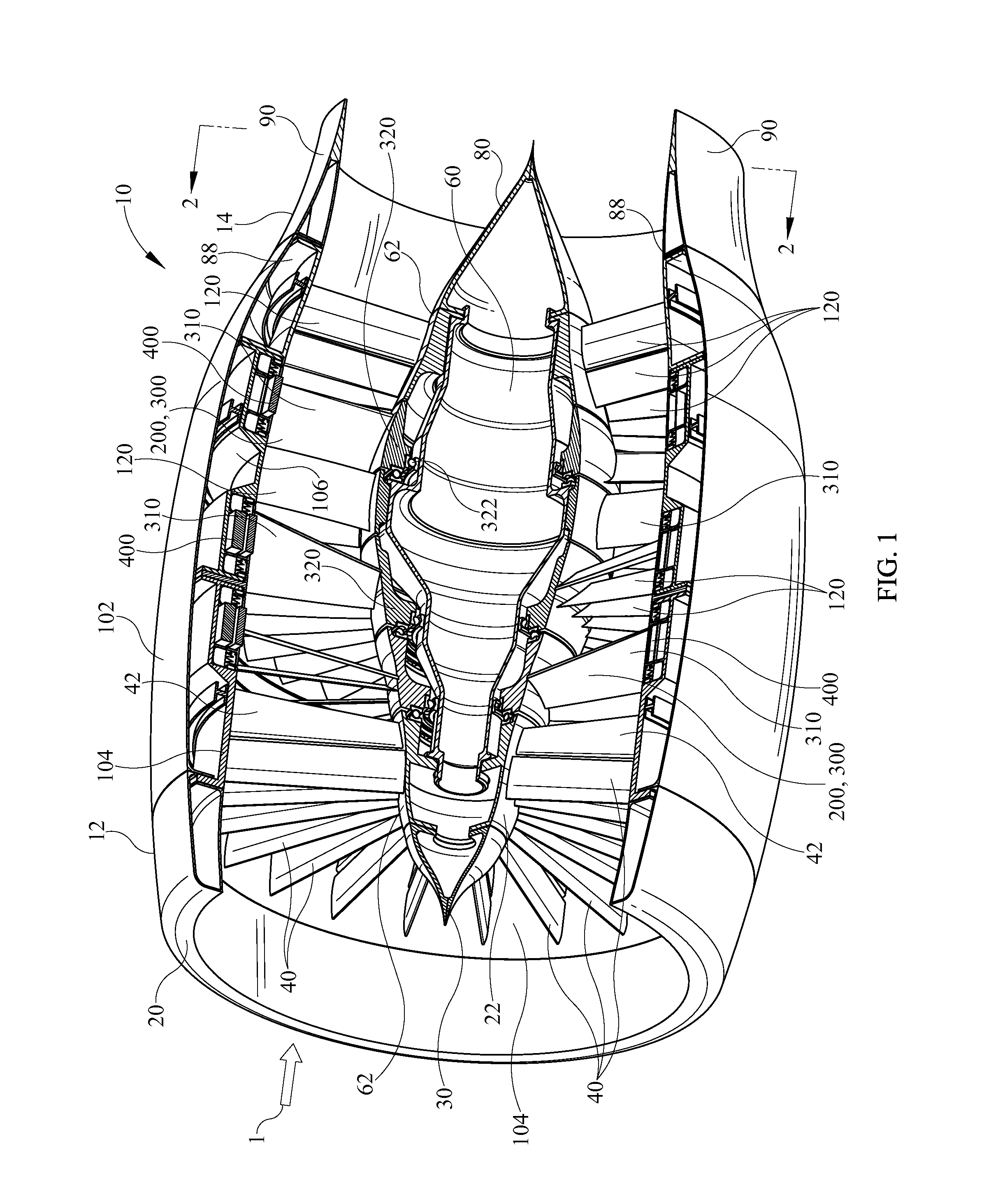
[0026]Referring now to the drawings and in particular FIG. 1, an exemplary depiction of an electromagnetic propulsive motor 10 in t...


PUM


Abstract

The invention provides an electromagnetic propulsive motor having a rotor capable of rotation around a shaft and having a plurality of radially disposed blades including blade tip portions for compressing a working fluid. The invention further provides a stator having a case frame, and a plurality of radially disposed vanes extending generally between said case frame and said shaft for directing the working fluid. A plurality of electromagnetic elements disposed within said rotor blades proximate the tip portions thereof interact electromagnetically with a plurality of electromagnetic elements disposed in said stator case frame to drive said rotor.

Description

CROSS-REFERENCE TO RELATED APPLICATIONS[0001]The present application claims the benefit (under 35 U.S.C. §119(e)) of U.S. Provisional Patent Application Ser. No. 61 / 345,412 filed May 17, 2010, and entitled “Electromagnetic Propulsive Motor”.FIELD OF THE INVENTION[0002]The present invention relates generally to aircraft propulsion systems, and more particularly to an electromagnetically driven compressive ducted fan propulsion system, herein referred to as an electromagnetic propulsive motor.BACKGROUND OF THE INVENTION[0003]Prior art gas turbine engines often employ a fan to draw in a working fluid, typically air, a compressor to compress the working fluid entering the engine, a combustor to burn the compressed air mixed with fuel, and a turbine that extracts work from the working fluid exiting the engine. Each of the aforementioned engine sections is typically comprised of one or more stages of rotating blades and concomitant vanes to direct the working fluid and extract work from t...

Claims


Application Information

Patent Timeline
Patent Type & Authority Patents(United States)
IPC IPC(8): H02K16/04H02K16/00
CPCH02K16/00H02K16/04H02K21/14H02K21/22H02K29/00H02K19/10H02K99/20H02K7/14F04D25/0606H02K1/22H02K5/22H02K1/12
Inventor USKERT, RICHARD CHRISTOPHER
Owner USKERT RICHARD CHRISTOPHER
Why Eureka
Try Eureka