Method and system for power generation

a power generation method and solar energy technology, applied in the direction of steam generation using solar heat, steam generation using hot heat carriers, lighting and heating apparatus, etc., can solve the problems of large land demands, affecting combustion, unstable and discontinuous, etc., and achieve the effect of solving the instability of solar energy

Inactive Publication Date: 2015-10-06
WUHAN KAIDI ENG TECH RES INST CO LTD
View PDF6 Cites 6 Cited by
  • Summary
  • Abstract
  • Description
  • Claims
  • Application Information

AI Technical Summary

Benefits of technology

[0010]In view of the above-described problems, it is one objective of the invention to provide a solar power generation method using a biomass boiler as an auxiliary heat source and a system related thereto. The method and system employ a biomass boiler as the auxiliary heat source, and combine the biomass energy and the solar power, thereby effectively solving the instability of the solar energy.
[0013]2) starting the solar concentrating collector; measuring a water temperature t3 at a water outlet main of the solar concentrating collector; opening a second control valve arranged between the water outlet main of the solar concentrating collector and the boiler drum when t3≧95° C., and opening a third control valve to supply water to a solar collector tube; introducing water into the boiler drum; adjusting the water supply to the solar collector tube to maintain t3≧95° C. according to the water temperature t3; and self-regulating by a control system of the turbonator unit, maintaining the water level of the boiler drum, a vapor pressure and a vapor temperature at a vapor outlet of the biomass boiler at rated values, and maintaining a steady operation of the turbonator unit;
[0030]As the highest temperature of the water heated by the solar concentrating collector is far lower than that of the water heated by a conventional boiler, the biomass boiler of the invention is provided with the auxiliary heater, the steam superheater, and the steam reheater. The water in the solar concentrating collector is introduced into the boiler drum and the auxiliary devices to be superheated or reheated, thereby achieving a temperature gradient operation of the solar heat energy, and improving a heat efficiency of the whole turbonator unit.
[0031]The power generation system of the invention is simplified by discarding a heat storage system (using a conduction oil or a molten salt as a heat storage medium) applied in a solar thermal power plant of prior arts, and is capable of alternatively or simultaneously making use of the solar heat source or the biomass heat source according to the change of the solar radiation due to the alternation of day and night and the change of the weather to maintain the continuous operation of the turbonator unit day and night, thereby effectively improving the availability of the solar energy power generation system, as well as solving the problem of the freeze prevention of the solar concentrating collector during winter.
[0032]The solar concentrating collector is placed on a roof of a biomass fuel storage field. Because the area of the biomass fuel storage field is large enough, this arrangement prevents the biomass fuel from the rain, and improves the land utilization of the solar thermal power plant using the biomass boiler as the second heat source.

Problems solved by technology

Furthermore, the capture of solar energy is affected by the change of the weather, thereby being unstable and discontinuous.
In order to maintain a continuous operation of the biomass boiler power plant, the biomass fuel storage field requires a large area, thereby resulting in large demands of land.
Furthermore, the biomass fuel stored in the open air is prone to wet, which affects the combustion, and some kind of biomass fuel is possible to auto-ignition in wet environment.
All these problems critically restrict the whole beneficial result of the biomass boiler power plant.
However, this technical scheme makes the system more complicated, and needs a higher cost.
Furthermore, the solar turbine has a larger volume, higher cost, and lower heat efficiency due to its special material and special structure.
More particularly, the system uses the molten salt as the heat storage medium, which makes the operation of the system become more difficult.
Thus, the molten slat is required to maintain at a temperature above 260° C. for long term, which, however, is energy consuming and is very difficult to realize.
In nocturnal period during winter or long term snowy and cloudy days when the temperature falls to 0° C. below, the above solar turbine is not capable of continuous operation.
Besides no beneficial results is produced; how to prevent the system from freezing is a difficult and energy consuming problem.

Method used


Image

  • Method and system for power generation
  • Method and system for power generation
  • Method and system for power generation

Examples


Embodiment Construction

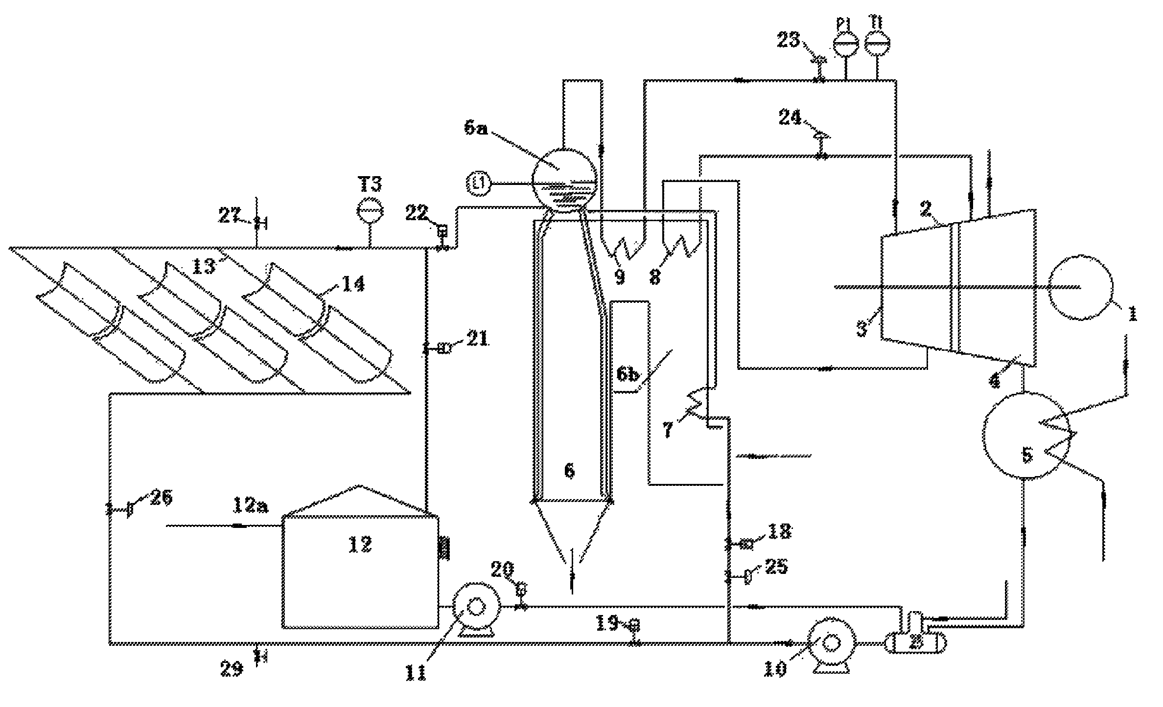
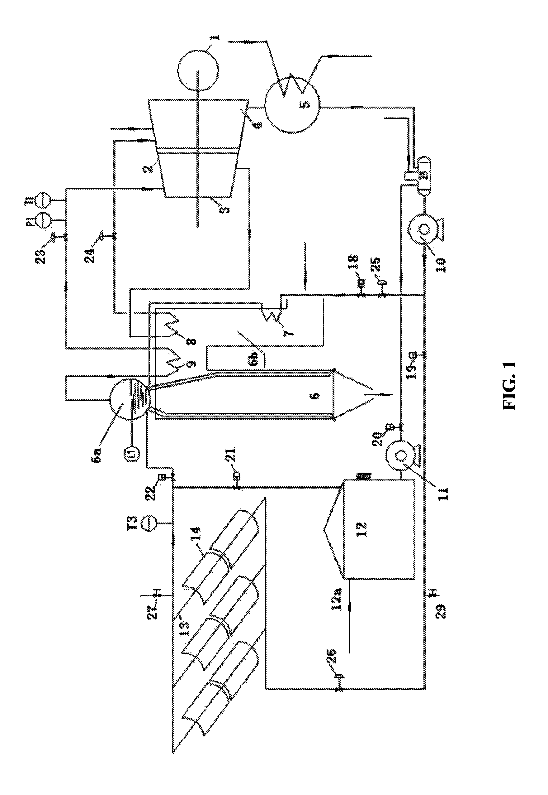
[0037]A solar power generation method using a biomass boiler as an auxiliary heat source and a system related thereto are specifically described hereinbelow combined with accompanying drawings.

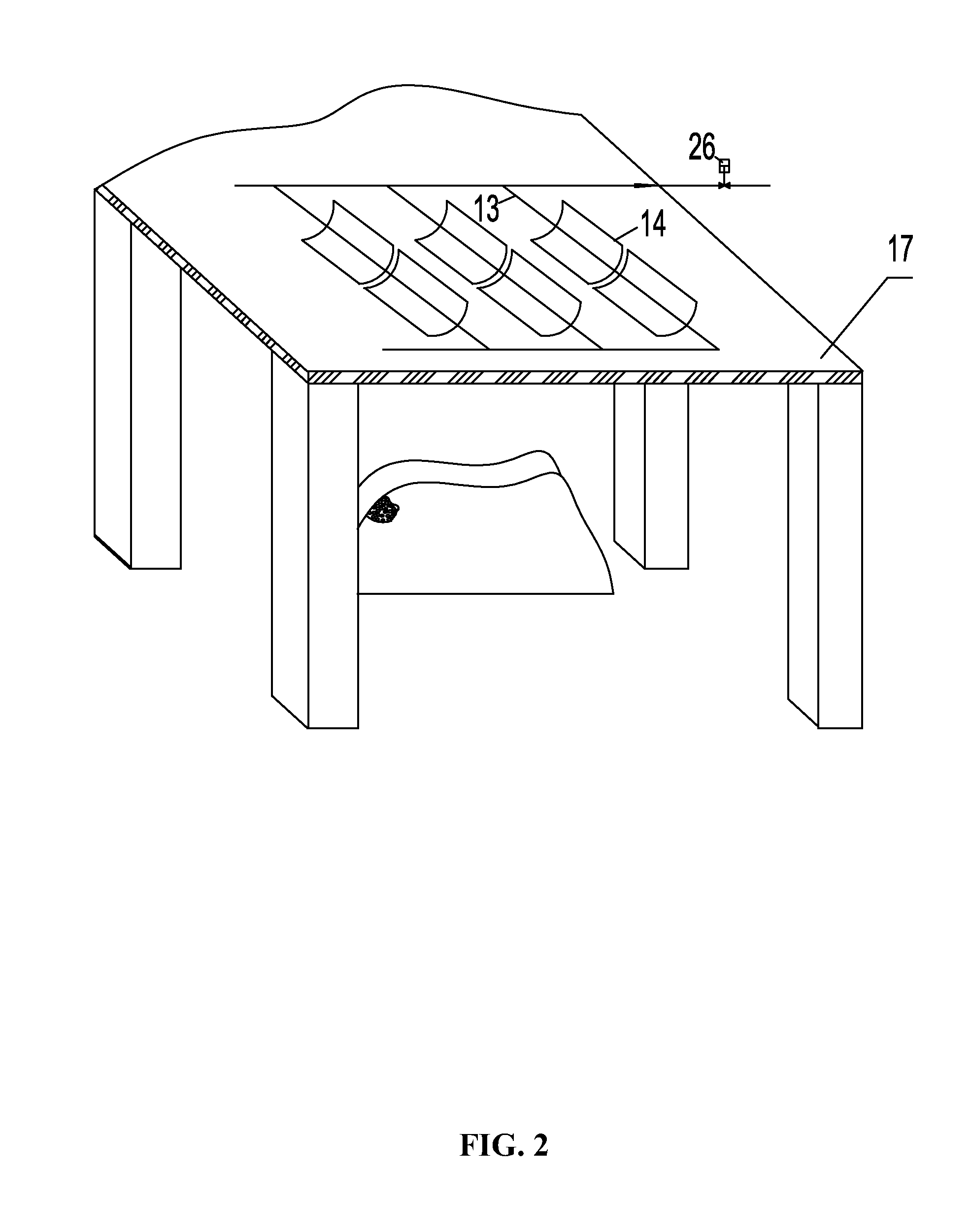
[0038]As shown in FIG. 1, 1 represents an electric generator; 2 represents a turbine; 3 represents a high pressure cylinder of the turbine 2; 4 represents a low pressure cylinder of the turbine 2; 5 represents a condenser; 6 represents a biomass boiler; 7 represents an auxiliary heater arranged inside a flue 6a of the biomass boiler 6; 8 represents a steam reheater arranged inside a flue 6a of the biomass boiler 6; 9 represents a steam superheater arranged inside a flue 6a of the biomass boiler 6; 10 represents a first water pump; 11 represents a second water pump of the biomass boiler 6; 12 represents a desalting water tank provided with a heat insulation layer for storing a soft water from a chemical water treatment device; 13 represents a solar collector tube; and 14 represents a parabolic ...


PUM


Abstract

A method of power generation, including: igniting a biomass boiler; starting a solar concentrating collector; measuring water temperature t3 at water outlet main of the solar concentrating collector; opening a second control valve arranged between the water outlet main and the boiler drum when t3 is greater or equal to 95° C.; closing the second control valve and the third control valve to prevent water in the solar collector tube from running and to maintain the water in a heat preserving and inactive state if the water temperature t3 decreases and t3 is less than 95° C.; turning the turbonator unit into a thermal power generation mode; opening a first control valve arranged between the water outlet main and a water supply tank if the water temperature t3 continues decreasing and when t3 is between 5 and 9° C.; and turning the turbonator unit into a biomass boiler power generation mode.

Description

CROSS-REFERENCE TO RELATED APPLICATIONS[0001]This application is a continuation-in-part of International Patent Application No. PCT / CN2011 / 078241 with an international filing date of Aug. 11, 2011, designating the United States, now pending, and further claims priority benefits to Chinese Patent Application No. 201010298986.7 filed Sep. 29, 2010. The contents of all of the aforementioned applications, including any intervening amendments thereto, are incorporated herein by reference. Inquiries from the public to applicants or assignees concerning this document or the related applications should be directed to: Matthias Scholl P. C., Attn.: Dr. Matthias Scholl Esq., 14781 Memorial Drive, Suite 1319, Houston, Tex. 77079.BACKGROUND OF THE INVENTION[0002]1. Field of the Invention[0003]The invention relates to a solar power generation method and system using a biomass boiler as an auxiliary heat source.[0004]2. Description of the Related Art[0005]Solar energy is characteristic in its wid...

Claims


Application Information

Patent Timeline
Patent Type & Authority Patents(United States)
IPC IPC(8): F03G6/00F01K7/22F22B1/00F22B1/18F03G6/06F24S90/00
CPCF03G6/00F01K7/22F03G6/065F22B1/006F22B1/18Y02E10/46F01K11/02F03G6/06F03G6/124F03G6/127
Inventor YANG, QINGPINGZHANG, YANFENGLI, HONG
Owner WUHAN KAIDI ENG TECH RES INST CO LTD
Why Eureka
Try Eureka