
Tunable ultrasound transmitter

a transmitter and ultrasound technology, applied in the field of acoustic signal transmitters, can solve the problems of image clutter, degraded image quality, and unimportant harmonics of higher than second-order according to thi techniques, and achieve the effect of simple and efficient implementation

Active Publication Date: 2015-10-20
FUJIFILM SONOSITE
View PDF9 Cites 8 Cited by
  • Summary
  • Abstract
  • Description
  • Claims
  • Application Information

AI Technical Summary

Benefits of technology

This patent invention provides a way to adjust the timing and speed of a transmitter's output waveform edges. It uses a system clock to provide precise timing and a programmable circuit to adjust the timing and slope of the waveform edges. This allows for fine control over the coarse output waveform produced by a transmitter.

Problems solved by technology

Harmonics higher than second-order are usually unimportant according to THI techniques because higher frequency harmonics rapidly attenuate as they propagate.
That is, the presence of second-order harmonics not generated by the subject tissue may be emitted or created by the ultrasound system acoustic transceiver and electronics and degrade the quality of the image, such as by causing image clutter, decreasing edge sharpness, etc.
In order for the pulse inversion THI technique to be effective, the paired burst signals must be equal and opposite, which has proven to be very difficult without implementing very complex circuits and / or highly linear transmitters.
A problem with using this approach, however, is that it results in high power dissipation, mostly by heat in the electronics rather than by the power being transferred to the acoustic element.
That is, transmitter circuits utilized to provide the high amplitude sine wave are somewhat inefficient resulting in appreciable amounts of energy being converted into heat rather than being applied to the acoustic elements for acoustic signal generation.
This then has several negative effects, including thermal management problems and, in the case of a battery powered instrument, rapid battery depletion.
These techniques at the present state of the art, however, have not been found to be particularly advantageous because of their circuit complexity and the lack of adequate, extremely fast power switching devices.

Method used


Image

  • Tunable ultrasound transmitter
  • Tunable ultrasound transmitter
  • Tunable ultrasound transmitter

Examples


Embodiment Construction

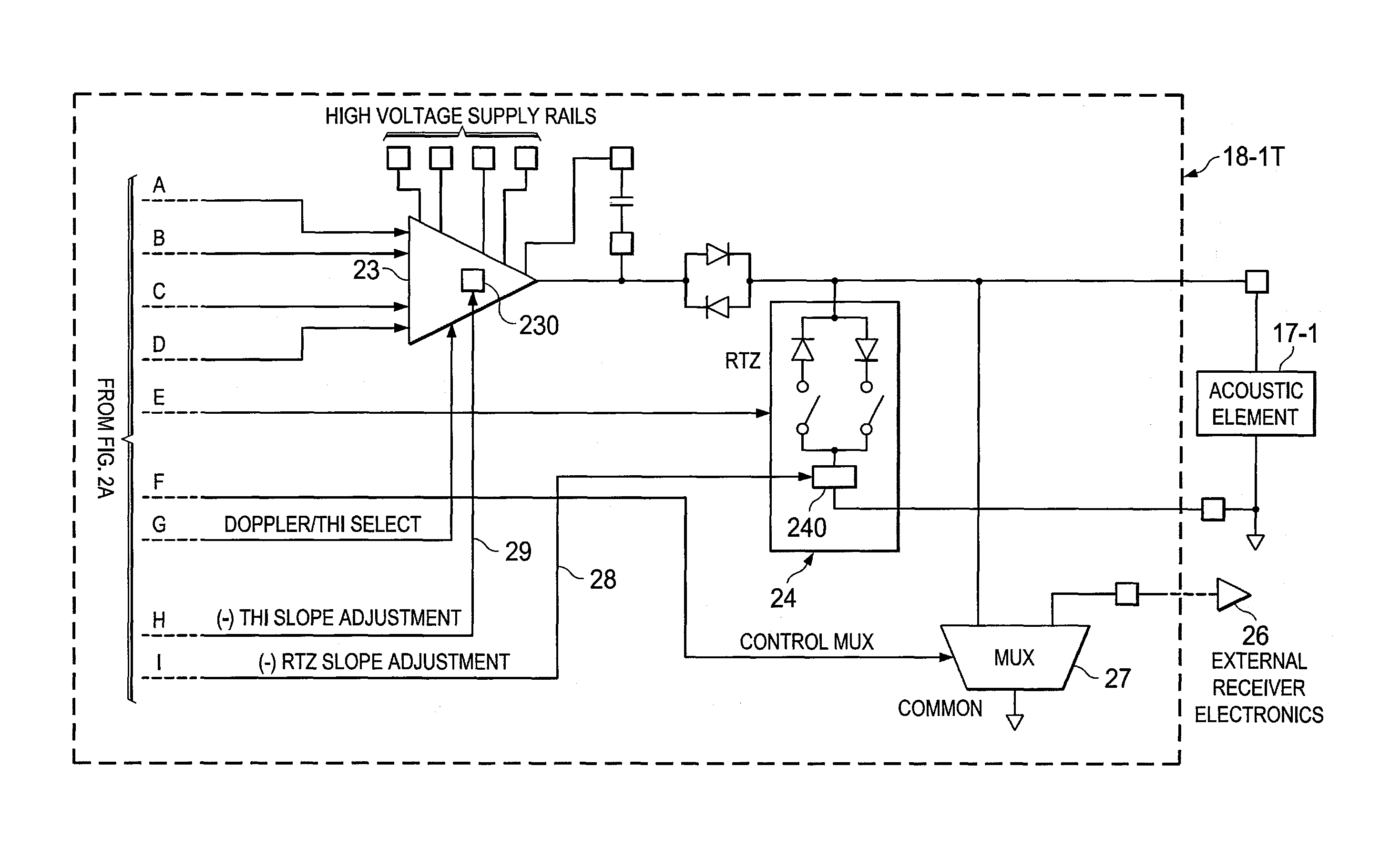
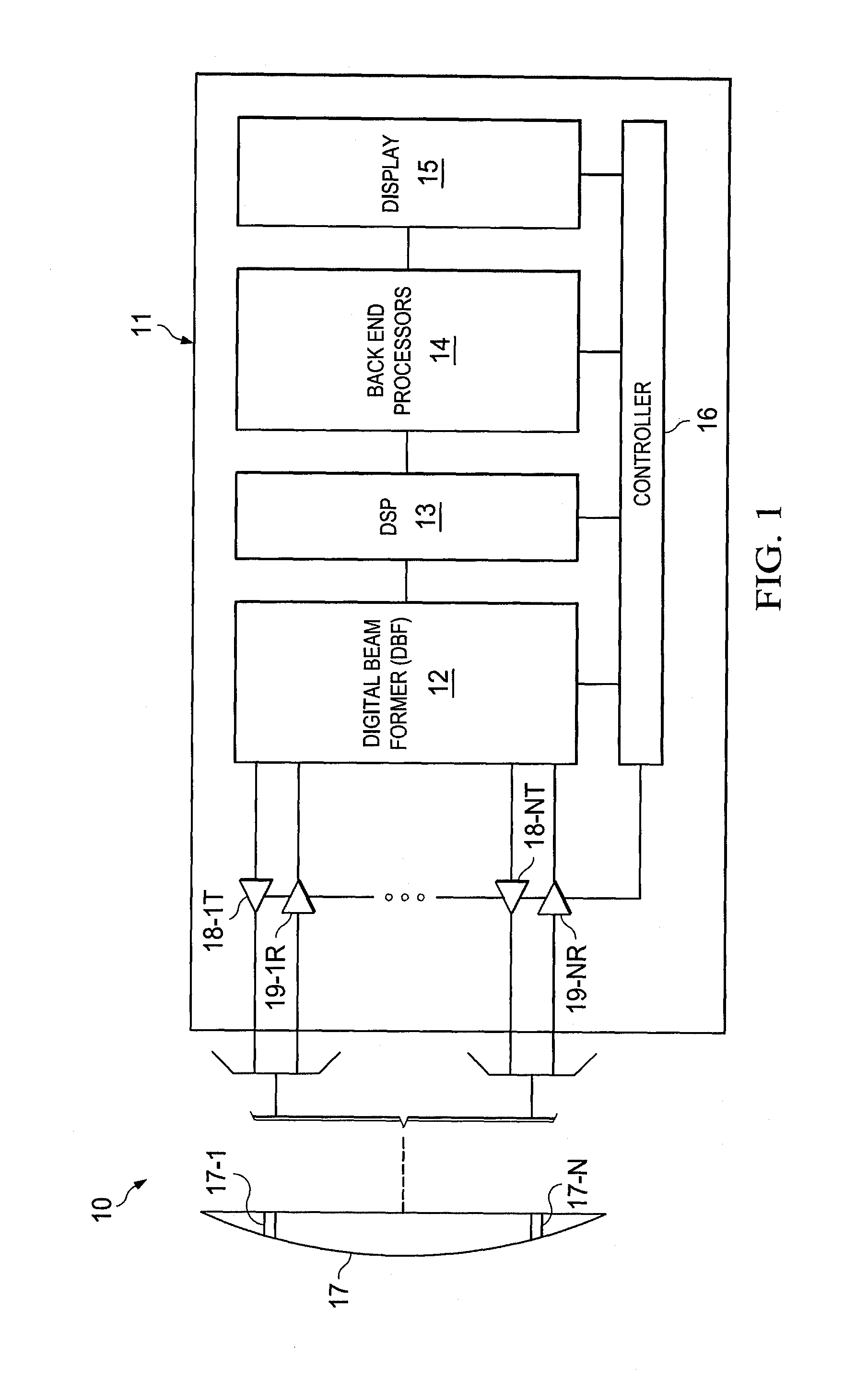
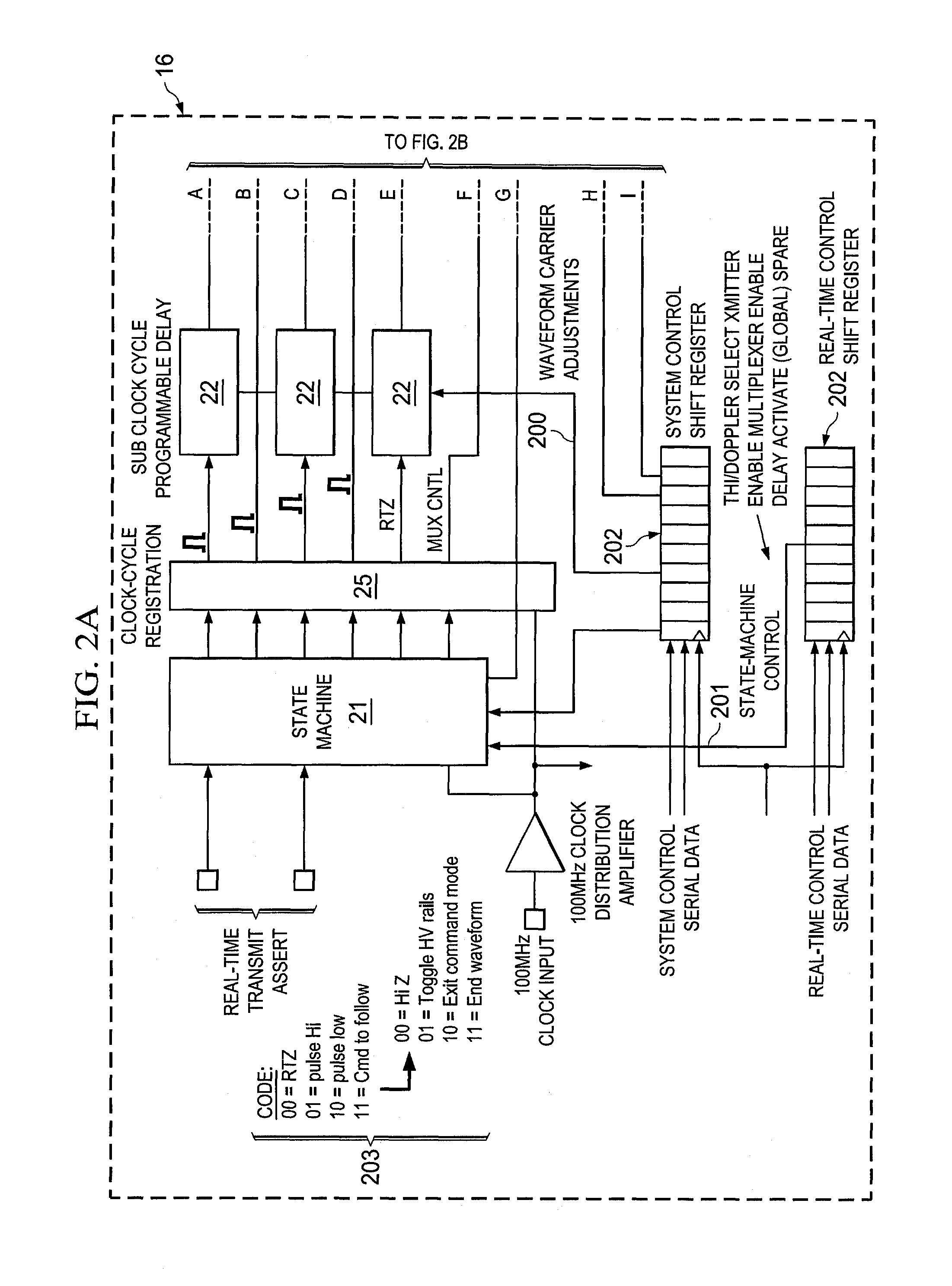
[0017]FIG. 1 shows one embodiment of an ultrasound system adapted according to embodiments of the invention. Ultrasound system 10 of the illustrated embodiment comprises an acoustic transceiver or transducer, shown as transducer 17, in electrical communication with a system unit, shown as system unit 11, operable to transmit and receive ultrasound signals for sonographic image generation.

[0018]Transducer 17 includes a plurality of transducer elements (e.g., acoustic elements), shown as elements 17-1 to 17-N. A variety of transducer element configurations will work with the concepts discussed herein. For example, elements 17-1 to 17-N may each comprise a piezoelectric crystal, a micro-machined transducer, an electromagnetic transducer, etc. Elements 17-1 to 17-N (together with their transmission line) will typically present a mathematically complex impedance, wherein mathematically complex in this context means that the impedance has a real component and an imaginary component. It sh...


PUM


Abstract

The use of power-efficient transmitters to establish acoustic wave energy having low undesirable harmonics is achieved by adjusting the transmitter output waveform to minimize the undesirable harmonics. In one embodiment, both the timing and slope of the waveform edges are adjusted to produce the desired output waveform having little or no second harmonics. In the embodiment, output waveform timing adjustments on the order of fractions of the system clock interval are provided. This then allows for very fine control of a coarsely produced waveform. In one embodiment, the user can select the fine tuning to match the transmitter output signal to a particular load transducer.

Description

TECHNICAL FIELD[0001]This disclosure relates to acoustic signal transmitters and more particularly to such transmitters having one or more tunable attributes for controlling harmonics.BACKGROUND OF THE INVENTION[0002]Ultrasound imaging has been utilized for years to view features and structures obfuscated by overlying material, surfaces, etc. For example, ultrasound systems are commonly used to provide imaging of subsurface tissue and features (e.g., blood flow) in the human body.[0003]Tissue Harmonic Imaging, “THI,” is a technique used in sonography to provide high quality images. THI relies on a phenomena whereby biological tissues (and / or other media) react to illumination by an acoustic wave (e.g., an ultrasound wave generated by an ultrasound imaging system) by generating second-order harmonics of the acoustic wave. Such tissue-generated second-order harmonics stem from the compression and decompression of tissue impacted by energy from acoustic sound waves transmitted into, or...

Claims


Application Information

Patent Timeline
IPC IPC(8): B06B1/02A61B8/00
CPCB06B1/0207B06B1/023B06B1/0223A61B8/44B06B1/0215A61B8/4444A61B8/4494A61B8/5207A61B8/5269A61B8/54G01S7/5202G01S7/52038G01S15/8963
Inventor STICE, JOHN R.WANG, YANWEISIEDENBURG, CLINTON T.LUNDBERG, ANDREW K.COUGHLIN, JUSTINNIELSEN, MAX E.
Owner FUJIFILM SONOSITE
Learn More