
Power converter with non-symmetrical totem pole rectifier and current-shaping branch circuits

a branch circuit and power converter technology, applied in the field of high efficiency rectifier solutions, can solve the problems of widespread adoption and use, circuits are not true diodes, and difficult to implement, and achieve the effect of high efficiency

Active Publication Date: 2015-10-20
BEL POWER SOLUTIONS INC
View PDF11 Cites 3 Cited by
  • Summary
  • Abstract
  • Description
  • Claims
  • Application Information

AI Technical Summary

Benefits of technology

The present invention provides a hybrid diode-less power converter that can efficiently convert power from an AC power source to a variable load. It includes a non-symmetrical arrangement of rectifying switches for rectifying an input AC voltage and shaping switches for shaping an input AC current. The shaping switches operate in Continuous Conduction Mode (CCM) based on an input AC current. The operation of each of the rectifying switches and shaping switches is further controlled, where the commutation time for the shaping switches is associated with a first voltage rise and fall time (e.g., less than 10 ns), and a commutation time for the rectifying switches is associated with a second voltage rise and fall time (e.g., at least 10 ns). This invention has high efficiency and is advantageous in various applications where an AC power source is used for power conversion.

Problems solved by technology

However, there are several limitations which make this solution relatively difficult to implement, and as a result it has not been widely adopted and used.
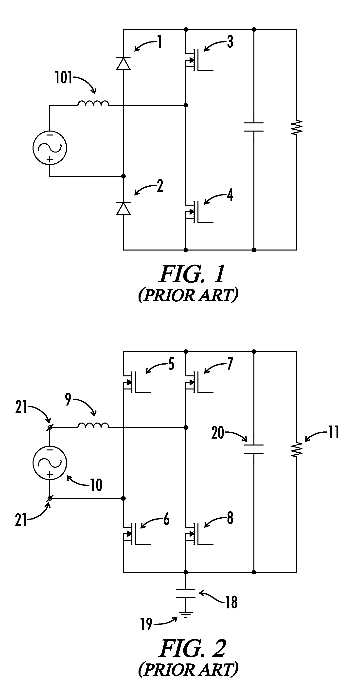
Because diodes 1 and 2 are forward-drop featured devices, this circuit is not a true diode-less solution and does not provide significant advantages when compared with other BL circuits.
While this solution benefits from the diode-less character of the circuit, it does, however, feature a significant disadvantage.
Slow body diodes of MOSFETs 7 and 8 significantly deteriorate the potential of the circuit in CCM by excessive reverse recovery current that induces high switching losses and may decrease the MOSFETs reliability when CCM control method is used.
This effect can be slightly enhanced by using MOSFETs with fast body diode, but with current state-of-the-art devices this does not achieve a significant improvement in efficiency over other conventional BL solutions.
Each of the three above-mentioned solutions suffer from other problems, however.
When a converter according to FIG. 2 is controlled at the boundary of DCM (BCM), the power handling capability is lower than its CCM controlled counterparts due to the fact that current in the smoothing choke 9 is periodically forced to fall to zero, and hence a high level of power density is difficult to achieve.
This method increases the power handling but still does not provide a very compact solution.
This increases conduction losses and decreases efficiency at light loads even though a ZVS technique recycles energy stored in output capacitance Coss of switches 7 and 8.
Another consequence of the larger negative current peak flowing through choke 9 that exists during valley switching, and is even larger in the case full ZVS behavior is targeted, is significant deterioration of input current THD when a standard constant on-time method is used within BCM control method.
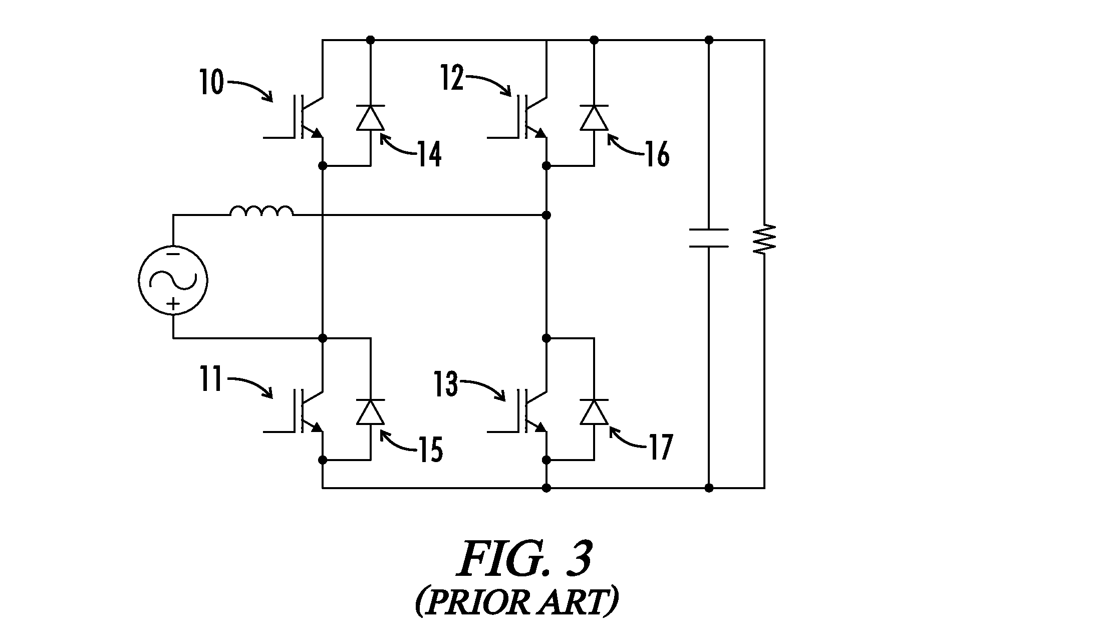
Vice output characteristics with typical forward-drop voltage and significant dynamic “tail current” losses cannot offer better efficiency as compared with a ZVS / valley controlled converter according to FIG. 2.
Because of that, total EM behavior of the converter is deteriorated.

Method used


Image

  • Power converter with non-symmetrical totem pole rectifier and current-shaping branch circuits
  • Power converter with non-symmetrical totem pole rectifier and current-shaping branch circuits
  • Power converter with non-symmetrical totem pole rectifier and current-shaping branch circuits

Examples


Embodiment Construction

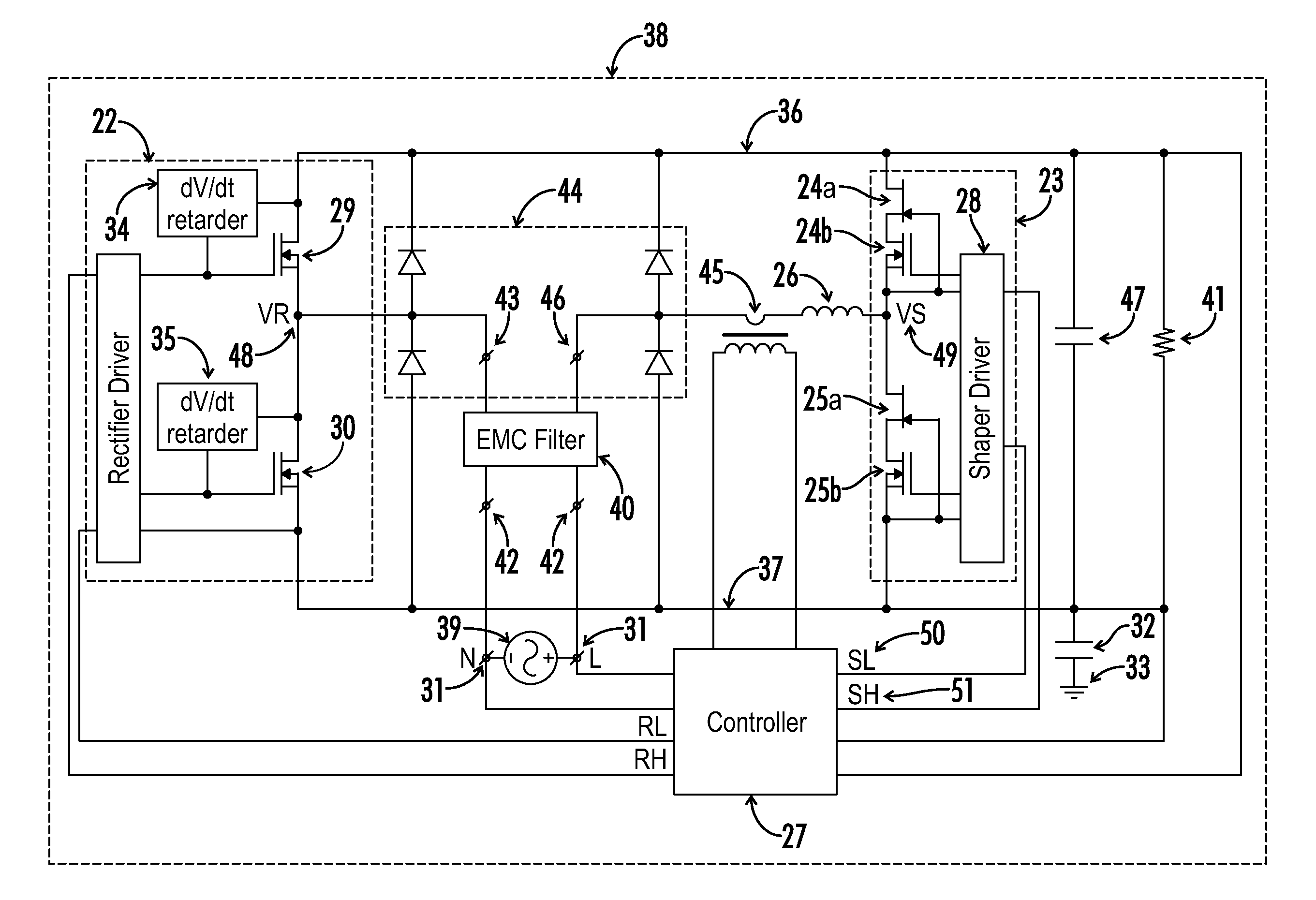
[0036]An embodiment of a Hybrid Diode-less Converter (“HDLC”) 38 according to the present invention is disclosed in FIG. 7.

[0037]In contrast to the prior art, where rectifying switches and shaping switches form a symmetrical structure, the HDLC architecture includes two branches, both featured by essentially different characteristics in terms of physical structure and also in terms of control method. The circuit architecture includes a silicon based rectifying branch 22 with essentially slowed-down switching behavior and a hybrid shaping branch 23 with a very high speed switching performance. Prior art totem pole rectifiers are mostly controlled with a BCM method where the current through smoothing choke is forced to fall periodically to zero (valley switching method) or to a predetermined negative current (ZVS technique). In comparison, the shaping switches 24 and 25 in the HDLC are essentially controlled by a CCM method. By doing this, the HDLC gains power density over prior art t...


PUM


Abstract

A hybrid diode-less power converter topology of the present invention converts power from an AC power source to a variable load with high efficiency. The power converter includes a non-symmetrical arrangement of rectifying switches for rectifying an input AC voltage and shaping switches for shaping an input AC current. The shaping switches are operated in Continuous Conduction Mode (CCM) based on an input AC current. Operation of each of the rectifying switches and shaping switches are further controlled wherein a commutation time for the shaping switches is associated with a first voltage rise and fall time (e.g., less than 10 ns), and a commutation time for the rectifying switches is associated with a second voltage rise and fall time (e.g., at least 100 ns), wherein the first voltage rise and fall time is less than the second voltage rise and fall time by a factor of nine or more.

Description

CROSS-REFERENCES TO RELATED APPLICATIONS[0001]This application claims benefit of the following patent application(s) which is / are hereby incorporated by reference: U.S. Provisional Patent Application No. 61 / 764,000 filed Feb. 13, 2013.[0002]A portion of the disclosure of this patent document contains material that is subject to copyright protection. The copyright owner has no objection to the reproduction of the patent document or the patent disclosure, as it appears in the U.S. Patent and Trademark Office patent file or records, but otherwise reserves all copyright rights whatsoever.BACKGROUND OF THE INVENTION[0003]This invention relates generally to the field of electrical power conversion, and more particularly to high efficiency rectifier solutions.[0004]A totem pole rectifier is a known bridge-less circuit used to rectify an AC line input voltage. It is understood as a solution with potential for highest achievable efficiency (>99%). Conventional versions of totem-pole recti...

Claims


Application Information

Patent Timeline
Patent Type & Authority Patents(United States)
IPC IPC(8): H02M7/219H02M1/42
CPCH02M7/219H02M1/4233Y02B70/126Y02B70/10H02M1/0085
Inventor FENO, IVAN
Owner BEL POWER SOLUTIONS INC
Learn More