Floatation separation apparatus, method of floatation separation, and method of manufacturing products using the same

a technology of floatation separation and floatation separation, which is applied in the direction of transportation and packaging, solid waste management, sustainable waste treatment, etc., can solve the problems of black parts appearing on hardened materials, unburned carbon-related problems, and physical properties of hardened materials may degrade, etc., to achieve separation efficient, simple structure, and simple structure

Inactive Publication Date: 2015-11-03
UNIVERSITY OF KITAKYUSHU
View PDF25 Cites 4 Cited by
  • Summary
  • Abstract
  • Description
  • Claims
  • Application Information

AI Technical Summary

Benefits of technology

[0022]According to the floatation separation method of the present invention, by taking out the liquid to be treated from the treatment tank main body and returning the liquid to the bottom portion of the treatment tank main body that narrows downward, the liquid to be treated is circulated while a vortex flow is formed, and at the same time air bubbles are supplied from the lower part of the treatment tank main body to the treatment tank main body. Consequently, air bubbles can be dispersed widely within the liquid, which allows the particles of materials to be treated to contact the air bubbles thoroughly. In addition, floatation separation can be performed without breaking the attachment between the air bubbles and the first component within the treatment tank main body, meaning that components within the material to be treated can be separated by floatation efficiently with a simple structure.
[0023]If fly ash is separated by floatation by the floatation separation method of the present invention, unburnt carbon contained in the fly ash can be separated efficiently with a simple structure. It is therefore possible to prevent unburnt carbon-related problems from occurring, and obtain a large amount of high-quality fly ash.
[0024]According to the method of manufacturing products using the device and the method of the present invention, a cement mixture is manufactured using fly ash from which unburnt carbon has been separated and removed thoroughly by the floatation separation method described above, meaning that a cement mixture using fly ash can be manufactured efficiently with a simple structure. In addition, since a large amount of fly ash can be used, a flat surface can be formed, for example, and a cement mixture that ensures various improved qualities after hardening, including unsusceptibility to dry shrinkage distortion and improved compressive strength, can be manufactured.

Problems solved by technology

It is known that if the unburnt carbon content is high, unburnt carbon-related problems may arise.
For example, when fly ash is used as a cement admixture, high fly ash content may increase the usage of admixtures such as AE agent, cause black portions to appear on a hardened material, or physical properties of the hardened material may degrade.

Method used


Image

  • Floatation separation apparatus, method of floatation separation, and method of manufacturing products using the same
  • Floatation separation apparatus, method of floatation separation, and method of manufacturing products using the same
  • Floatation separation apparatus, method of floatation separation, and method of manufacturing products using the same

Examples


first embodiment

[First Embodiment]

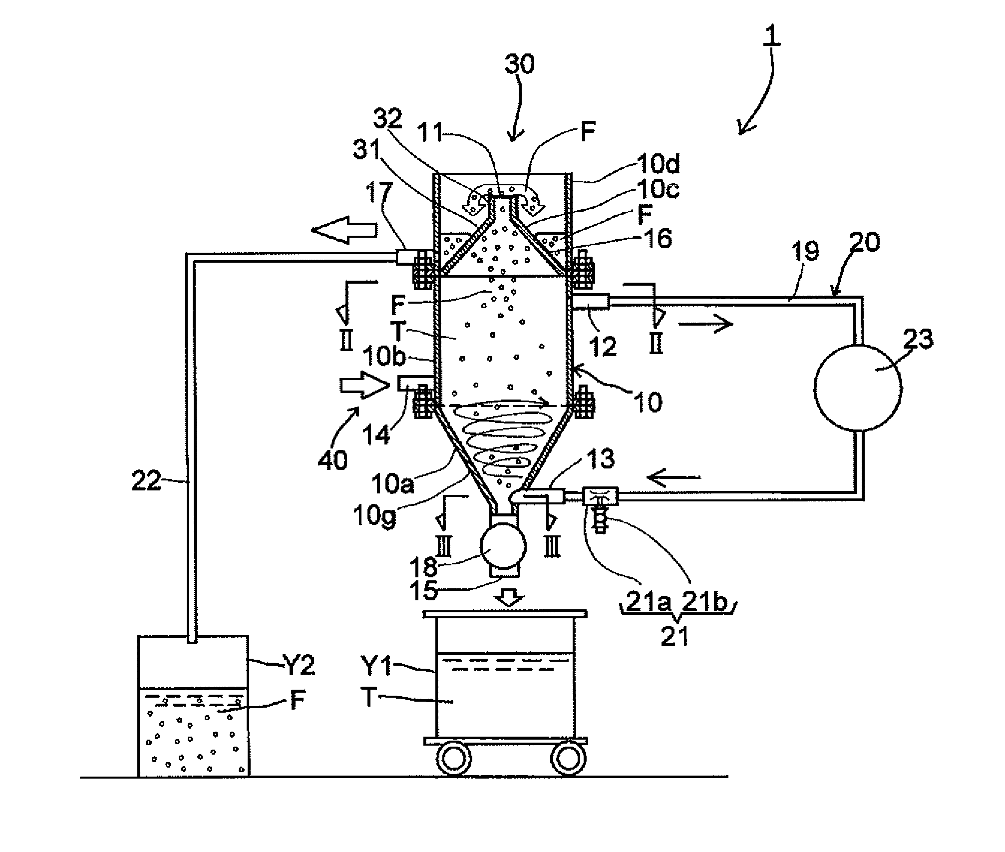
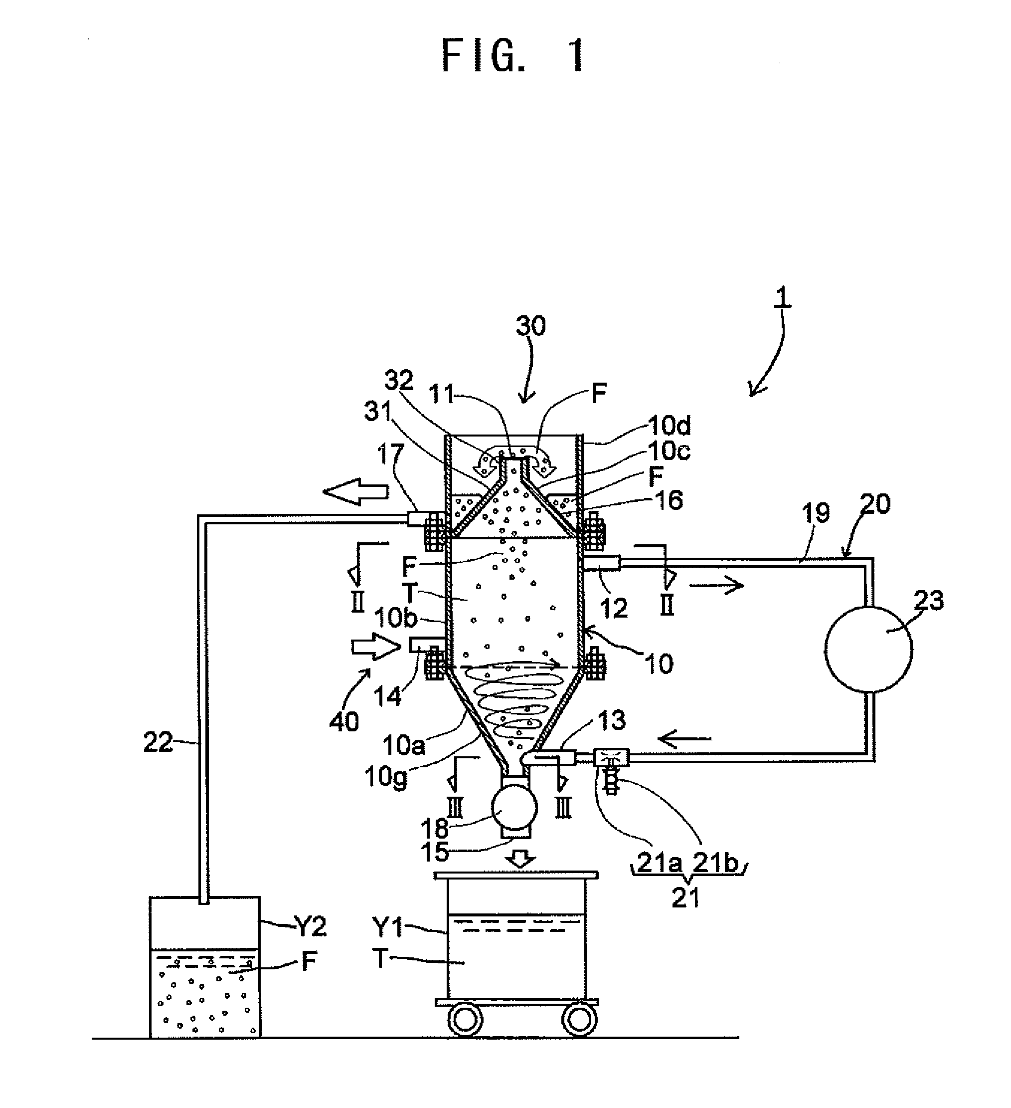
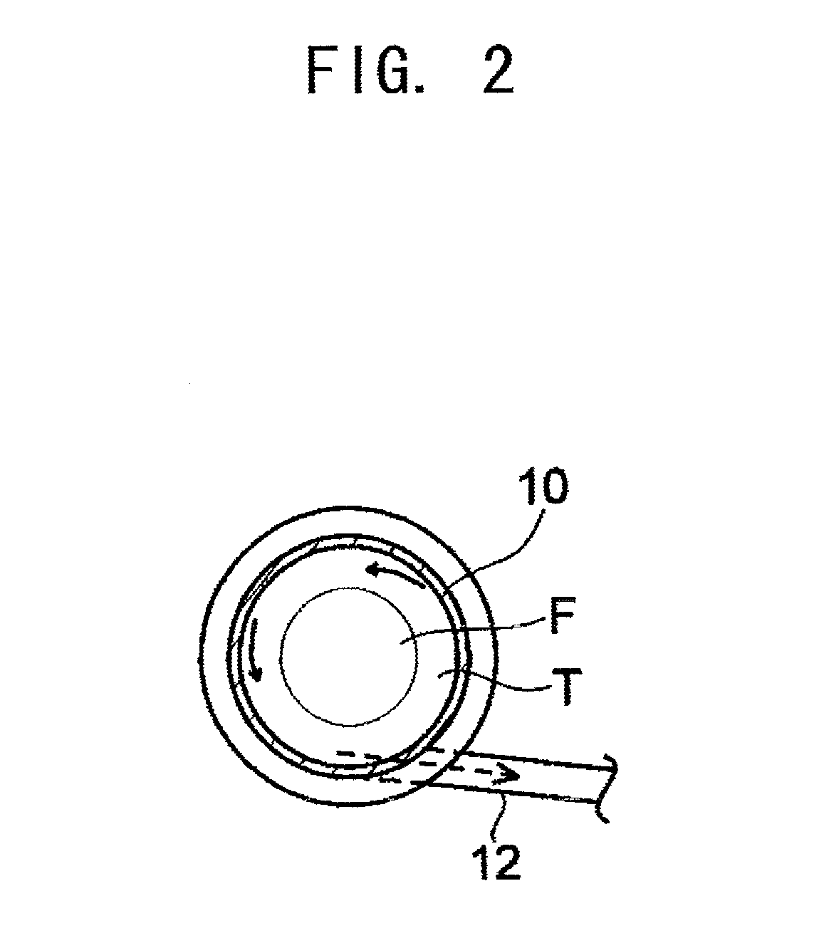
[0035]The floatation separation apparatus and method of the first embodiment will be described first by referring to FIGS. 1 to 3.

[Floatation Separation Apparatus]

[0036]The floatation separation apparatus is used to subject a liquid containing particles of materials to be treated to floatation separation.

[0037]Any materials, including solids or powder such as fly ash, metals, and minerals, general drainage and other effluent, industrial waste liquids containing heavy metals, slurry such as sludge, can be treated, provided that they contain particles capable of forming a dispersion liquid when used as they are or by being dispersed into various dispersion media.

[0038]Particles in the material to be treated contain a first component having relatively low wettability and a second component having wettability higher than that of the first component, and may contain other components. Each component may be a pure material or a mixture. For example, if the particles of th...

second embodiment

[Second Embodiment]

[0095]A fly ash slurry manufacturing device and method using the floatation separation apparatus in the first embodiment and its method will be described by referring to FIG. 4.

[0096]The manufacturing device in this embodiment is intended to treat fly ash containing unburnt carbon, and manufacture slurry containing reformed fly ash having unburnt carbon, which is impurity, in low content.

[0097]The target of treatment ranges widely from the fly ash having unburnt carbon content as low as approximately 3 wt % to as high as approximately 25 wt %. Conventionally unwanted and unused fly ash, which is therefore treated as industrial waste, can also be treated.

[0098]As shown in FIG. 4, the device in this embodiment includes a pretreatment device 50, a floatation separation apparatus 1 similar to the one in the first embodiment, and a concentrating device 60. With this device, the pretreatment device 50 implements the pretreatment process of pre-treating fly ash and thus ...

example 1

[0128]Using the fly ash generated in a thermal power plant in Okinawa (raw ash A) and the fly ash generated in Asahi Kasei No. 3 thermal power plant (raw ash B), floatation separation was conducted using the floatation separation apparatus 1 shown in FIG. 1 under the same conditions, and the amount of unburnt carbon was measured. The amount of unburnt carbon in raw ash A before treatment accounted for 7.72 wt %, and the unburnt carbon content in raw ash B was 6.84 wt %.

[0129]Measurement of the amount of unburnt carbon was conducted by taking out each tail when 30 minutes, 60 minutes, 120 minutes, and 180 minutes have elapsed, and by conducting an ignition loss test for each tail.

[0130]The results obtained are shown in Table 1 and FIG. 5. The chart in FIG. 5 illustrates the results listed in Table 1. The horizontal axis represents treatment time, whereas the vertical axis represents the ignition loss.

[0131]

TABLE 1Ignition loss (wt %)Floatation separationType of ashdurationABRaw ash7....


PUM

PropertyMeasurementUnit
particle diameteraaaaaaaaaa
diameteraaaaaaaaaa
frequencyaaaaaaaaaa

Abstract

By storing a liquid to be treated in a treatment tank main body 10 having a bottom portion 10g that narrows downward, with particles of materials to be treated dispersed therein, taking out the liquid to be treated from a position lower than the liquid level of the treatment tank main body 10, and returning the liquid to the bottom portion 10g of the treatment tank main body 10, thereby circulating the liquid to be treated while forming a vortex flow within the treatment tank main body 10, and at the same time supplying air bubbles from the lower part of the treatment main unit 10, a first component contained in froths is separated from a second component, which is less susceptible to floatation, contained in the liquid to be treated.

Description

TECHNICAL FIELD[0001]The present invention relates to a device for separating particles dispersed in a liquid to be treated by floatation separation, the method of the floatation separation, and a method of manufacturing products using the device and the method by decreasing unburnt carbon contained in fly ash, for example.BACKGROUND ART[0002]Fly ash discharged in large amounts as a byproduct from a pulverized coal firing boiler of a thermal power plant, etc. is used in many fields, as a cement raw material, for example.[0003]Fly ash usually contains unburnt carbon. It is known that if the unburnt carbon content is high, unburnt carbon-related problems may arise. For example, when fly ash is used as a cement admixture, high fly ash content may increase the usage of admixtures such as AE agent, cause black portions to appear on a hardened material, or physical properties of the hardened material may degrade. For these reasons, fly ash has not been used in large amounts.[0004]To solve...

Claims


Application Information

Patent Timeline
Patent Type & Authority Patents(United States)
IPC IPC(8): B03D1/14C04B18/08C02F1/24B03D1/24C04B28/02
CPCC02F1/24B03D1/1418B03D1/1462B03D1/1475B03D1/24C04B18/08C04B28/02C04B14/06C04B20/02B03D1/247B03D2203/08C02F2301/024C02F2301/026Y02W30/92Y10T137/2076Y02W30/91B03D1/14B03B5/28
Inventor MATSUFUJI, YASUNORITAKASU, KOJITATSUMI, KIYOTAKA
Owner UNIVERSITY OF KITAKYUSHU
Why Eureka
Try Eureka