Molded-in insert and method for fiber reinforced thermoplastic composite structure

a fiber reinforced thermoplastic composite and insert technology, applied in the direction of threaded fasteners, manufacturing tools, mechanical equipment, etc., can solve the problems of poor retention of inserts, improper fit, and known press-fit inserts and swaged inserts designed for press-fit installation in metal structures or parts, and achieve high strength retention and high strength retention

Active Publication Date: 2015-11-10
THE BOEING CO
View PDF9 Cites 6 Cited by
  • Summary
  • Abstract
  • Description
  • Claims
  • Application Information

AI Technical Summary

Benefits of technology

[0012]This need for a molded-in insert and method for high strength retention in fiber reinforced thermoplastic composite parts or structures is satisfied. As discussed in the below detailed description, embodiments of the molded-in insert or fitting and method for high strength retention in fiber reinforced thermoplastic composite parts or structures and methods may provide significant advantages over existing devices and methods.

Problems solved by technology

Methods for installing inserts into composite and metal structures or parts may include, for example, mold in place methods, such as where molded-in inserts are installed during molding, or for example, more expensive post-molding methods, such as where press-fit inserts or swaged inserts are installed after molding.
However, known press-fit inserts and swaged inserts designed for press-fit installation in metal structures or parts may not work well with fiber reinforced thermoplastic composite structures or parts due to the non-ductile nature of the fiber reinforced thermoplastic composite material.
Such non-ductile fiber reinforced thermoplastic composite material may lead to over-stressing of the material around the insert if the fit is too tight or may lead to poor retention of the insert if the fit is too loose, thus resulting in an improper fit.
Thus, a proper fit of such known press-fit and swaged inserts may be difficult to attain with non-ductile materials such as fiber reinforced thermoplastic composite material.
Moreover, post-molding methods for installing known press-fit inserts or swaged inserts may incur increased labor and manufacturing costs, increased set-up and operating time, and increased final part cost.
However, such known molded-in insert 30 and molded-in threaded insert 32 may not work well with compression molded fiber reinforced thermoplastic composite structures or parts due to difficulties in filling the small radii 44 or the sharp internal corners 42 of the groove 38 during the molding process. FIG. 3 is an illustration of a cross-sectional top view of the known molded-in insert 30 showing the knurled surface 34 with sharp knurls 36 after being compression molded in place in a carbon fiber reinforced thermoplastic composite part 50 comprised of a carbon fiber reinforced thermoplastic composite material 52 having reinforcing carbon fibers 54 in a resin matrix 55.
Such void areas 56 of incomplete consolidation may undermine retention strength of molded-in inserts within the fiber reinforced thermoplastic composite parts or structures.

Method used


Image

  • Molded-in insert and method for fiber reinforced thermoplastic composite structure
  • Molded-in insert and method for fiber reinforced thermoplastic composite structure
  • Molded-in insert and method for fiber reinforced thermoplastic composite structure

Examples


Embodiment Construction

[0048]Disclosed embodiments will now be described more fully hereinafter with reference to the accompanying drawings, in which some, but not all of the disclosed embodiments are shown. Indeed, several different embodiments may be provided and should not be construed as limited to the embodiments set forth herein. Rather, these embodiments are provided so that this disclosure will be thorough and complete and will fully convey the scope of the disclosure to those skilled in the art.

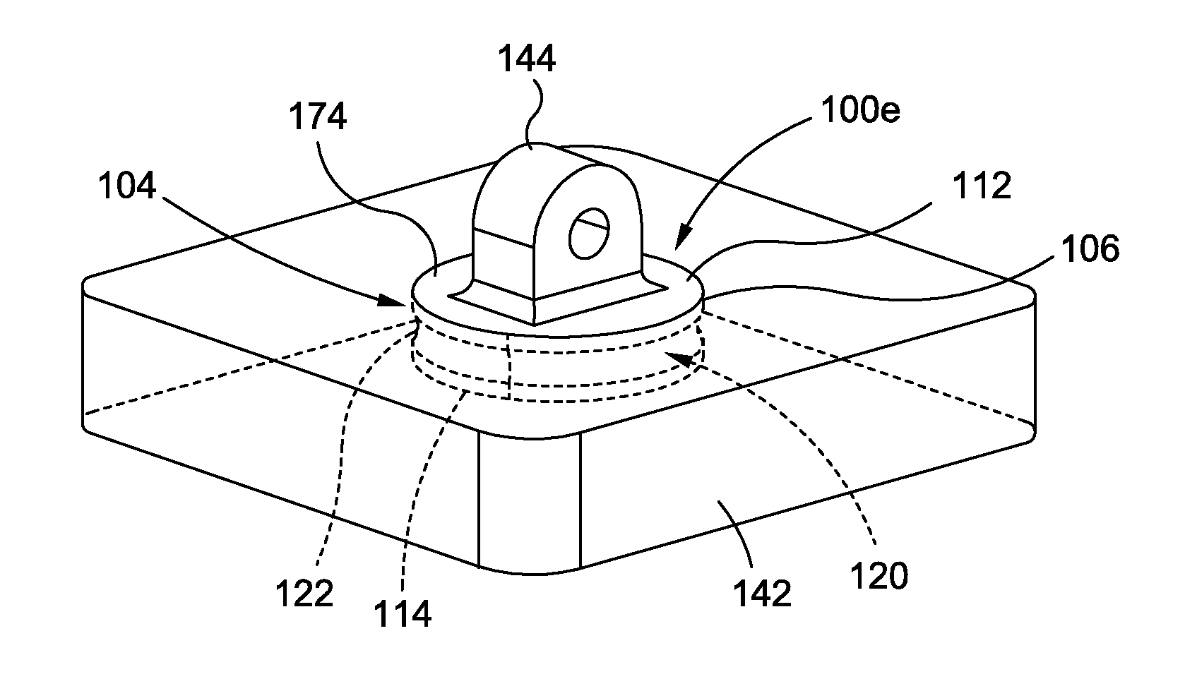
[0049]Now referring to the Figures, FIG. 1 is an illustration of a perspective view of an exemplary aircraft 10 that may be made from one or more composite parts 102 incorporating one or more advantageous embodiments of a molded-in insert 100 (or embodiments of molded-in inserts 100a-100h as shown in FIGS. 6-18B) of the disclosure. As shown in FIG. 1, the aircraft 10 comprises a fuselage 12, a nose 14, a cockpit 16, wings 18 operatively coupled to the fuselage 12, one or more propulsion units 20, a tail ve...


PUM

PropertyMeasurementUnit
groove radiusaaaaaaaaaa
lengthaaaaaaaaaa
pressureaaaaaaaaaa

Abstract

In an embodiment of the disclosure, there is provided a molded-in insert for high strength retention in a fiber reinforced thermoplastic composite structure. The insert has a cylindrical body and at least one circumferential groove formed in the cylindrical body, the groove having a substantially concave configuration, having a groove radius of 0.025 inch or greater, and having the groove radius greater than or equal to a groove depth.

Description

BACKGROUND[0001]1) Field of the Disclosure[0002]The disclosure relates generally to inserts for use in structures, and more particularly, to molded-in inserts for use in composite structures and parts in aircraft, spacecraft, and other vehicles.[0003]2) Description of Related Art[0004]Inserts may be used in the assembly of composite and metal structures or parts for various transport vehicles, such as aircraft, spacecraft, rotorcraft, watercraft, automobiles, trucks, buses, or other transport vehicles. Such inserts may be used to receive mating fasteners, provide attachment points for multi-part assemblies, and provide load transfer points. Examples of such inserts may include press-fit inserts, swaged inserts, molded-in inserts, threaded inserts, or other suitable inserts or fittings.[0005]Methods for installing inserts into composite and metal structures or parts may include, for example, mold in place methods, such as where molded-in inserts are installed during molding, or for e...

Claims


Application Information

Patent Timeline
Patent Type & Authority Patents(United States)
IPC IPC(8): F16B1/00B29C31/08B29C70/68B29C39/10B29C45/14F16B37/12B29K105/20
CPCB29C70/682B29C39/10B29C45/14311B29C45/14631B29C70/683F16B37/122B29K2105/20Y10T403/47B29C43/18B29C2043/181B29K2101/12B29K2105/06
Inventor FISHER, JR., EDWARD MCMURRAYCARTER, BRIAN ALLEN
Owner THE BOEING CO
Why Eureka
Try Eureka