Exhaust aftertreatment system where an activator material is added to the reductant fed to the catalytic converter

a catalytic converter and activator material technology, applied in the direction of machines/engines, mechanical equipment, separation processes, etc., can solve the problems of high nox levels, increased particulates, and only possible high engine efficiency, and achieve small nox conversion effect, enhanced catalytic activity, and increased catalytic material efficiency

Inactive Publication Date: 2015-11-10
VOLVO TRUCK CORP
View PDF18 Cites 0 Cited by
  • Summary
  • Abstract
  • Description
  • Claims
  • Application Information

AI Technical Summary

Benefits of technology

[0011]An advantage with the present invention is that a conversion over the catalytic material is increased, especially at low temperatures, compared to the catalytic reaction without the presence of the activator material, so that the active temperature range of the catalyst material is closer to the exhaust gas temperature than otherwise. Another advantage with the present invention is that a wide range of different catalytic materials can be used which results advantageously in a reduction of costs. Still another advantage of the present invention is that an alternative selective catalytic reduction process to the procedure with ammonia or urea can be maintained. This results in a reduction of an amount of reducing agent which had to be carried on board the vehicle as well as in a less failure-sensitive process due to alternative substances to urea and / or ammonia. Further, an unwanted emission of ammonia in case of unfavourable process conditions is avoided.
[0012]The catalytic converter arrangement can have one or several catalytic devices, like a NOx reducing catalyst, a soot removing component such as a catalyst or particulate filter or any component and / or catalyst which is feasible for a person skilled in the art. Furthermore, the catalytic devices may be arranged in any arbitrary order. In an expedient arrangement the NOx reducing catalyst is arranged downstream of the soot catalyst. Moreover, the one or more dosing interfaces may be arranged downstream of the combustion engine and upstream of the catalytic converter arrangement and particularly upstream of the NOx reducing catalyst. Further, the one or more dosing interfaces may comprise an injector, a nozzle, a vaporizer, an atomizer and / or any other interface which is feasible for a person skilled in the art. The reducing agent and the activator material may be applied via the same dosing interface or different interfaces and / or at the same time, as a mixture or temporally offset compared to each other. Particularly, they may be added via the same dosing interface into the exhaust gas as a mixture. The ratio of activator material to reducing agent can range from substantially 0 wt-% up to substantially 50 wt-% (wt-%=weight percent) and in extreme cases up to substantially 60 wt-% or even up to substantially 70 wt-%. Alternatively, it is also possible to apply the reducing agent in one or more cylinders of the combustion engine e.g. via post-injection. Expediently, the dosing interface for input of the activator material to the exhaust gas is arranged in, on or at the exhaust gas path downstream of the combustion engine.
[0013]The reducing agent is an independent component relative to the activator material. The activator material takes effect on the catalytic material and increases the efficiency of the catalytic material at lower temperatures compared to the efficiency without the presence of the activator material.
[0014]According to a favourable embodiment of the invention, the activator material can comprise at least one oxygenated hydrocarbon. Preferably the activator material consists of or comprises one oxygenated hydrocarbon. The amount of activator material which is added in one application process may be dependent on the temperature of the catalyst. The same may apply for the amount of the reducing agent. Generally speaking, at high temperatures of the catalyst the activator material has only a small effect on NOx conversion and is avoidable. Similarly, at low temperatures of the catalyst when the reducing agent and / or the activator material work inefficiently the reducing agent and / or the activator material may be not injected at all. In a certain temperature range in between these two temperature boundaries a mixture of reducing agent and activator material works best. Thus, at high temperatures of the catalyst the amount of added activator material could be reduced to substantially zero and at lower temperatures of the catalyst within the said temperature range it could go up to substantially 50 wt-% or in some extreme cases even higher up to substantially 60-70 wt-%. Hence, the mixture is favourably adjusted according to the temperature of the catalyst. Expediently, the amount of the mixture out of the activator material and the reducing agent added in one application process may depend on the amount of NOx. The amount of the mixture in respect to the NOx amount ranges from substantially 0.1:1 on weight basis up to substantially 10:1 and preferably from substantially 0.5:1 on weight basis up to substantially 5:1 and particularly advantageously from substantially 1:1 on weight basis up to substantially 3:1. The oxygenated hydrocarbon can have any state of aggregation which is feasible for a person skilled in the art and is preferably a fluid in the state of application. Therefore, cooling devices for the dosing interface may also be provided. Due to the invention the enhancement of the catalytic activity and efficiency of the catalytic material can be easily obtained.
[0015]According to another favourable embodiment of the invention the activator material may comprise at least one oxygenated hydrocarbon of ether type and preferably an ether out of a group consisting of or comprising: triglyme, diglyme, monoglyme, diethyl ether (DEE), dipropyl ether. By means of such a substance a material with known characteristics can be used.
[0016]In yet another example embodiment of the present invention the activator material may comprise at least triglyme. The amount of triglyme which is added in one application process depends, as stated above, on the temperature of the exhaust gas at the catalyst. Thus, a substance can be provided which is advantageously liquid in the state of handling and application to the exhaust gas. Additionally, triglyme is also liquid in a storage condition in the vehicle, which is typically in a range between −50° C. to +50° C. Therefore, accidental freezing or crystallization of the activator material could be prevented securely for the operating process of the vehicle. Consequently, a plugging of application devices like the dosing interfaces could be avoided. Additionally, costly heating devices to avoid e.g. freezing of the activator material could be dispensed. Furthermore, due to the liquid state of triglyme a mixture with an also liquid reducing agent is easy and efficient to produce and to handle. With triglyme as activator material, a smaller amount of substances which are applied in the form of the reducing agent and the activator material to the exhaust gas in the SCR process is needed compared with SCR by urea-water solution and corresponds approximately to a reduction of up to 50-80 wt-%.

Problems solved by technology

Said high engine efficiency is however only possible at an elevated combustion temperature at which high NOx levels are inevitable.
Moreover, a suppression of NOx formation by internal means (such as a specific air / fuel ratio) has the tendency to cause an increase in particulates, known as the NOx-particulates trade off.
Furthermore, an excess of oxygen in the exhaust gas from a diesel engine prevents the use of stoichiometric 3-way-catalyst technology for reduction of NOx as is used in gasoline engine cars from the late eighties of the last century.
However, a large amount of this urea-water solution is needed and has to be fuelled and carried on-board in addition to the vehicle fuel.
However, the NOx conversion is generally lower than for SCR by ammonia or urea especially at lower temperatures and a large amount of hydrocarbon is needed.
However, the former would require a large tank for the hydrogen and possibly additional safety measures and the latter a reformer system on board the vehicle.
Similarly, at low temperatures of the catalyst when the reducing agent and / or the activator material work inefficiently the reducing agent and / or the activator material may be not injected at all.
Additionally, costly heating devices to avoid e.g. freezing of the activator material could be dispensed.
Further, due to the use of the fuel as reducing agent only an additional small container for the activator material is needed on board the vehicle.

Method used


Image

  • Exhaust aftertreatment system where an activator material is added to the reductant fed to the catalytic converter
  • Exhaust aftertreatment system where an activator material is added to the reductant fed to the catalytic converter
  • Exhaust aftertreatment system where an activator material is added to the reductant fed to the catalytic converter

Examples


Embodiment Construction

[0033]In the drawings, equal or similar elements are referred to by equal reference numerals. The drawings are merely schematic representations, not intended to portray specific parameters of the invention. Moreover, the drawings are intended to depict only typical embodiments of the invention and therefore should not be considered as limiting the scope of the invention.

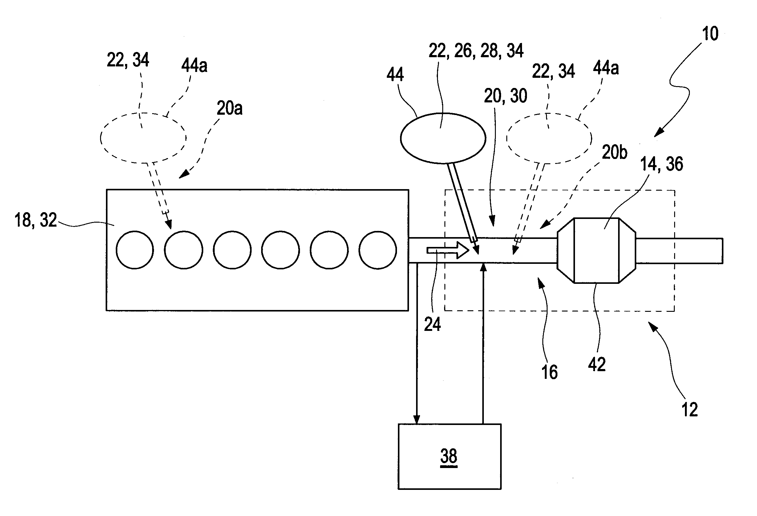
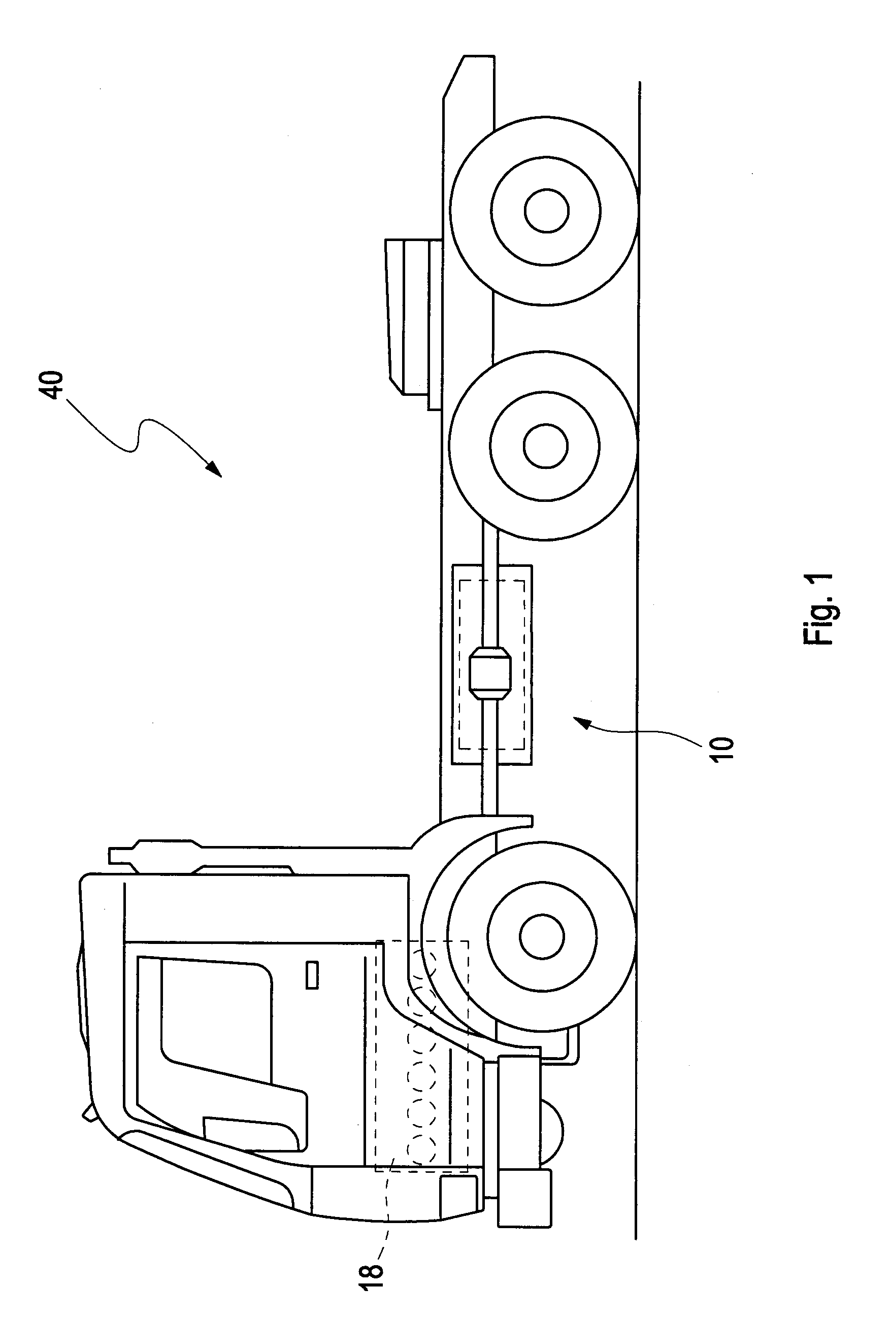
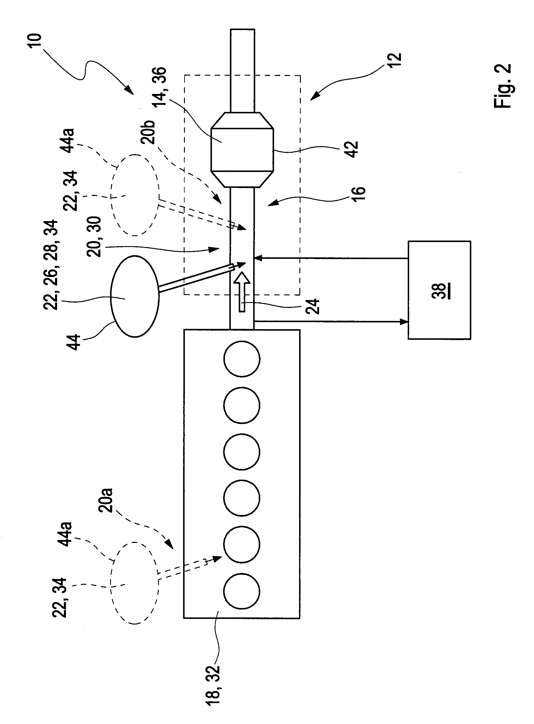
[0034]FIG. 1 depicts schematically a vehicle 40 with a combustion engine 18 and an exhaust gas after treatment system 10 downstream of the combustion engine 18. An example embodiment of the exhaust gas after treatment system is illustrated in detail in FIG. 2.

[0035]The exhaust gas after treatment system 10 comprises a catalytic converter arrangement 12 which is arranged in an exhaust gas path 16 or an exhaust pipe, respectively, downstream of the combustion engine 18, which is embodied as a diesel engine 32. The catalytic converter arrangement 12 comprises a component for reducing a soot content, such as a catalyst f...


PUM

PropertyMeasurementUnit
temperatureaaaaaaaaaa
temperaturesaaaaaaaaaa
temperatureaaaaaaaaaa

Abstract

An exhaust gas after treatment system includes a catalytic converter arrangement with at least one catalytic material, wherein the catalytic converter arrangement is arranged in an exhaust gas path downstream of a combustion engine, and further includes one or more dosing interfaces for feeding at least one reducing agent for reducing an NOx content in the exhaust gas. The one or more dosing interfaces are arranged to feed at least one activator material to the exhaust gas. The activator material causes an enhancement of a catalytic activity of the catalytic material compared to the catalytic activity of the catalytic material without the presence of the activator material at least in a given temperature range.

Description

BACKGROUND AND SUMMARY[0001]The invention relates to an exhaust gas after treatment system and a method for treating an exhaust gas in an exhaust gas after treatment system as well as a vehicle with an exhaust gas after treatment system.[0002]Present regulatory conditions in the automotive market have led to an increasing demand to improve fuel economy and reduce emissions in present vehicles. These regulatory conditions must be balanced with the demands of a consumer for high performance and quick response for a vehicle.[0003]A diesel engine has an efficiency of up to about 52% and is thus the best converter of fossil energy. NOx emission concentration, i.e. the emission of nitrogen oxides NO and NO2, is dependent upon local oxygen atom concentration and the local temperature in the combustion process in the engine. Said high engine efficiency is however only possible at an elevated combustion temperature at which high NOx levels are inevitable.[0004]Moreover, a suppression of NOx ...

Claims


Application Information

Patent Timeline
Patent Type & Authority Patents(United States)
IPC IPC(8): F01N3/36F01N3/18F01N3/20B01D53/90F01N3/28B01D53/94
CPCF01N3/18B01D53/90B01D53/9431F01N3/208F01N3/2066B01D53/9418B01D2251/208B01D2251/21B01D2252/2025B01D2255/104B01D2255/106B01D2255/1021B01D2255/1023B01D2255/1025F01N3/2896F01N3/36F01N2610/01F01N2610/03F01N2610/1406F01N2610/146F01N2900/1402F01N2900/1404F01N2900/1602Y02T10/24Y02A50/20Y02T10/12
Inventor ERKFELDT, SARA
Owner VOLVO TRUCK CORP
Why Eureka
Try Eureka