Composite membranes comprising a sulfonated polyarylether and their use in forward osmosis processes

a polyarylether and composite membrane technology, applied in the direction of membranes, filtration separation, separation processes, etc., can solve the problems of insufficient water permeation and separation performance of known fo membranes, detrimental to feed solutions, limited number of commercially available fo membranes, etc., and achieve high water flux and superior properties.

Inactive Publication Date: 2015-11-24
BASF AG +1
View PDF10 Cites 4 Cited by
  • Summary
  • Abstract
  • Description
  • Claims
  • Application Information

AI Technical Summary

Benefits of technology

[0016]One object of the invention is to provide novel membranes suitable in particular forward osmosis (FO) processes which can overcome the disadvantages of the state of art, in particular having superior properties (e.g. high water flux) in use for forward osmosis.
[0017]It was surprisingly found that the composite membrane comprising a high content of sulfonated polymer in the substrate layer exhibit a structure having the following advantageous characteristics:

Problems solved by technology

For example, forward osmosis (FO) can operate without high hydraulic pressures which are necessary in the reverse osmosis process and high temperatures which are necessary in the distillation and may be detrimental to the feed solution.
The major problems in use of forward osmosis today are e.g. the limited number of commercially available FO membranes, insufficient water permeation and separation performance of known FO membranes and the lack of desirable draw solutions depended on the intended use of osmosis product.
Membranes, which are designed for reversed osmosis processes can often not be applied in the forward osmosis process due to their thick and dense support layer, which is necessitated to withstand high pressure in the reversed osmosis process and which causes decreased water flux and high salt leakage in the FO process.
However, said support layer substrate consists of finger like macrovoid which may reduce the membrane integrity in the long term process of use in osmosis processes, in particular in forward osmosis processes.

Method used


Image

  • Composite membranes comprising a sulfonated polyarylether and their use in forward osmosis processes
  • Composite membranes comprising a sulfonated polyarylether and their use in forward osmosis processes
  • Composite membranes comprising a sulfonated polyarylether and their use in forward osmosis processes

Examples


example 2

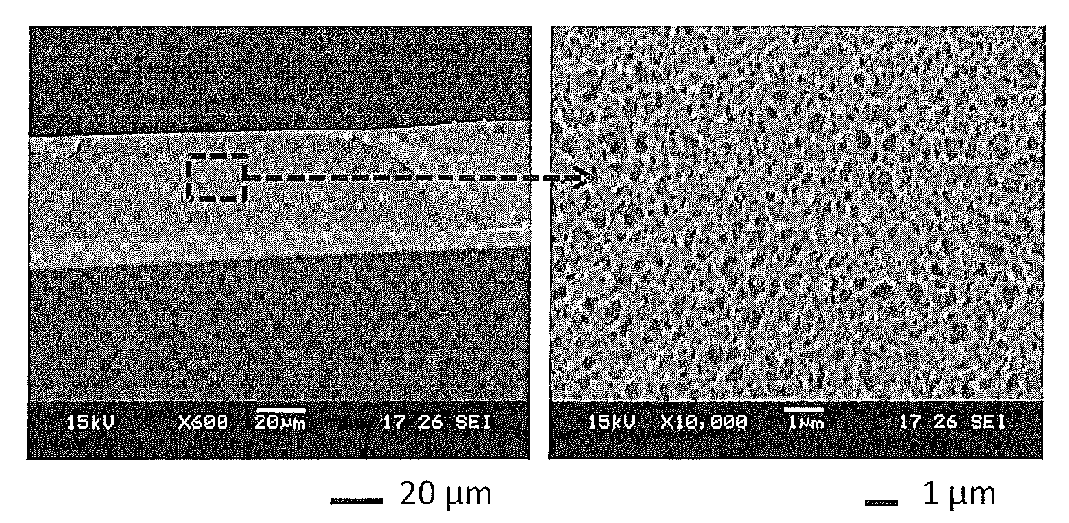
Production of Thin Film Layer (F) onto Substrate Layer (S)

[0225]The substrate (substrate layer (S)) based on sulfonated polyarylethers as produced in Example 1 was used for formation of a thin polyamide layer (film layer (F)). The formation of a polyamide layer onto the substrate layer was based on the interfacial polymerization. The substrate layer was first immersed in 2 wt % of MPD (metaphenylendiamine) in deionized water (DI water) for 1 minute. Thereafter, filter paper was used to remove the water droplets in the membrane surface. Subsequently, the top surface of membranes was brought into contact with the 0.05 wt % TMC (trimesoyl chloride) solution in n-hexane for 15 seconds. The resultant membrane was dried at 60° C. for 1 minute, followed by drying in the air for 2 minutes. The resultant membrane was further cleaned in deionized water before use in forward osmosis process (FO). After this process, a thin polyamide film (film layer (F)) was formed on the substrate layer (S).

[...

example 3

Forward Osmosis Process Using Thin Film Composite Membrane

[0228]The thin film composite membrane produced as described in Examples 1 and 2 was tested in a forward osmosis (FO) experiment.

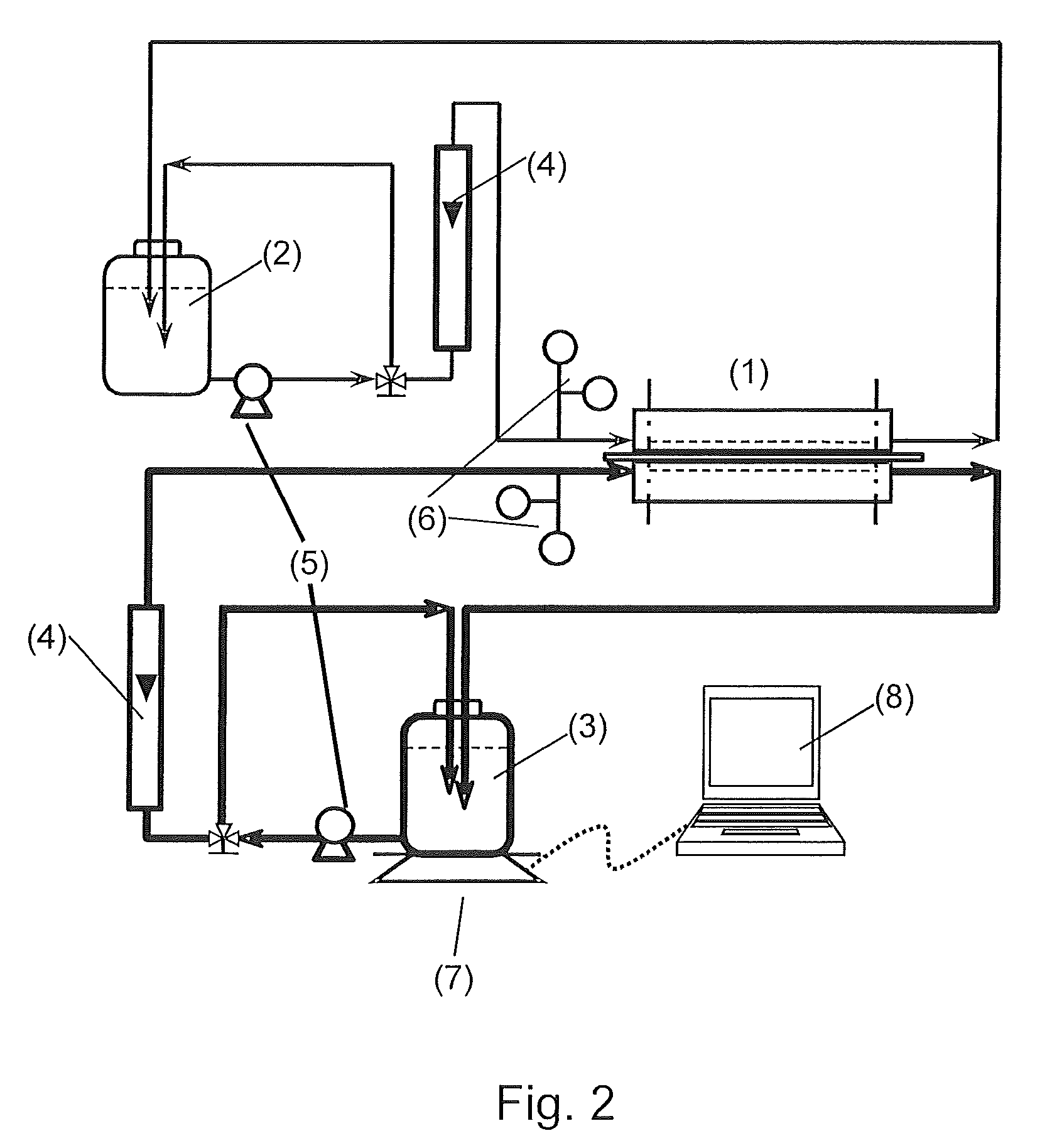
[0229]FO experiments were conducted on a lab-scale circulating filtration unit. The schematic diagram of the filtration unit is shown in FIG. 2.

[0230]The crossflow permeation cell (1) was a plate and frame design with a rectangular channel on each side of the membrane. The feed solution (2) and the draw solution (3) were in storage tanks and circulated via pumps (5). The solution flows were adjusted using flow meters (4). The solution flow velocities during the FO process were kept at 6.4 cm / s for both feed solution (2) and draw solution (3) which was co-currently flowed through the cell channels. The temperature and the pressure of each solution were measured (6). The temperatures of the feed and draw solutions were maintained at 22±0.5° C. The pressures at two channel inlets were kept at 1.0 psi.

[...

example 4

Forward Osmosis Process Using Sea Water

[0246]A forward osmosis process using the thin film composite membrane produced as described in Examples 1 and 2 was carried out similar to Example 3 using seawater as feed solution instead of deionized water. The feed solution concentration consisted of 3.5 wt % NaCl and the draw solution concentration (NaCl) was varied from 2 M (mol / L) to 5 M (mol / L).

[0247]The water flux in the FO mode and the PRO mode using varying draw solution concentration (NaCl) are summarized in Table 2:

[0248]

TABLE 2Water flux of inventive composite membrane using sea water(3.5 wt % NaCl solution) as feed in FO and PRO mode.Concentrationof NaClFO modePRO modedraw solutionWater fluxWater flux[mol / L][LMH][LMH]213.515319.521422.525.5525.527.0

[0249]It can be found that the water flux of thin film composite FO membrane can reach 15 LMH using 2M NaCl as draw solution tested under PRO mode.


PUM

PropertyMeasurementUnit
weight ratioaaaaaaaaaa
wt %aaaaaaaaaa
molecular weightaaaaaaaaaa

Abstract

The present invention is directed to thin film composite membrane (TFC membrane) comprising a substrate layer (S) based on a sulfonated polymer, e.g. a sulfonated polyarylether, and a polyamide film layer (F) and further to a method for their preparation. Furthermore, the present invention is directed to osmosis processes, in particular to forward osmosis (FO) processes, using said membrane.

Description

CROSS REFERENCE TO RELATED APPLICATIONS[0001]This application claims benefit (under 35 USC 119(e)) of U.S. Provisional Application 61 / 480,381, filed Apr. 29, 2011, which is incorporated by reference.BACKGROUND OF THE INVENTION[0002]The present invention is directed to thin film composite membranes (TFC membranes) comprising a substrate layer (S) based on a sulfonated polymer, e.g. a sulfonated polyarylether, and a polyamide film layer (F) and further to a method for their preparation. Furthermore, the present invention is directed to osmosis processes, in particular to forward osmosis (FO) processes, using said membrane.[0003]The development and application of membrane technologies (e.g. dialysis, membrane filtration such as nano-, ultra- and micro-filtration and osmosis processes) is one of the most significant recent advances in chemical, environmental, and biological process engineering.[0004]In view of global water scarcity, particularly in drought-prone and environmentally poll...

Claims


Application Information

Patent Timeline
Patent Type & Authority Patents(United States)
IPC IPC(8): C08G14/00B01D71/82B01D71/80B01D69/12B01D71/56B01D71/68B01D69/10B01D67/00C02F1/44B01D61/00C02F103/08
CPCC02F1/445B01D67/0006B01D67/0009B01D69/10B01D69/125B01D71/56B01D71/68B01D71/80B01D71/82B01D61/002B01D2323/40C02F2103/08Y02A20/131
Inventor WEBER, MARTINMALETZKO, CHRISTIANWARZELHAN, VOLKERWIDJOJO, NATALIACHUNG, TAI-SHUNG
Owner BASF AG
Why Eureka
Try Eureka