

Membrane technology for use in a methanol-to-propylene conversion process
a technology of methanol and methanol, applied in the field of methanol-to-propylene (mtp) conversion process, to achieve the effect of reducing raw material loss and increasing product yield
- Summary
- Abstract
- Description
- Claims
- Application Information
AI Technical Summary
Benefits of technology
Problems solved by technology
Method used
Image

Examples
example 1
Comparative Example—Conventional MTP Process (not in Accordance with the Invention)
[0122]The calculations that follow were performed using a computer process simulation program (ChemCad 6.3.2, ChemStations, Houston, Tex.) which was modified with differential element subroutines for the membrane separation steps (as applicable).
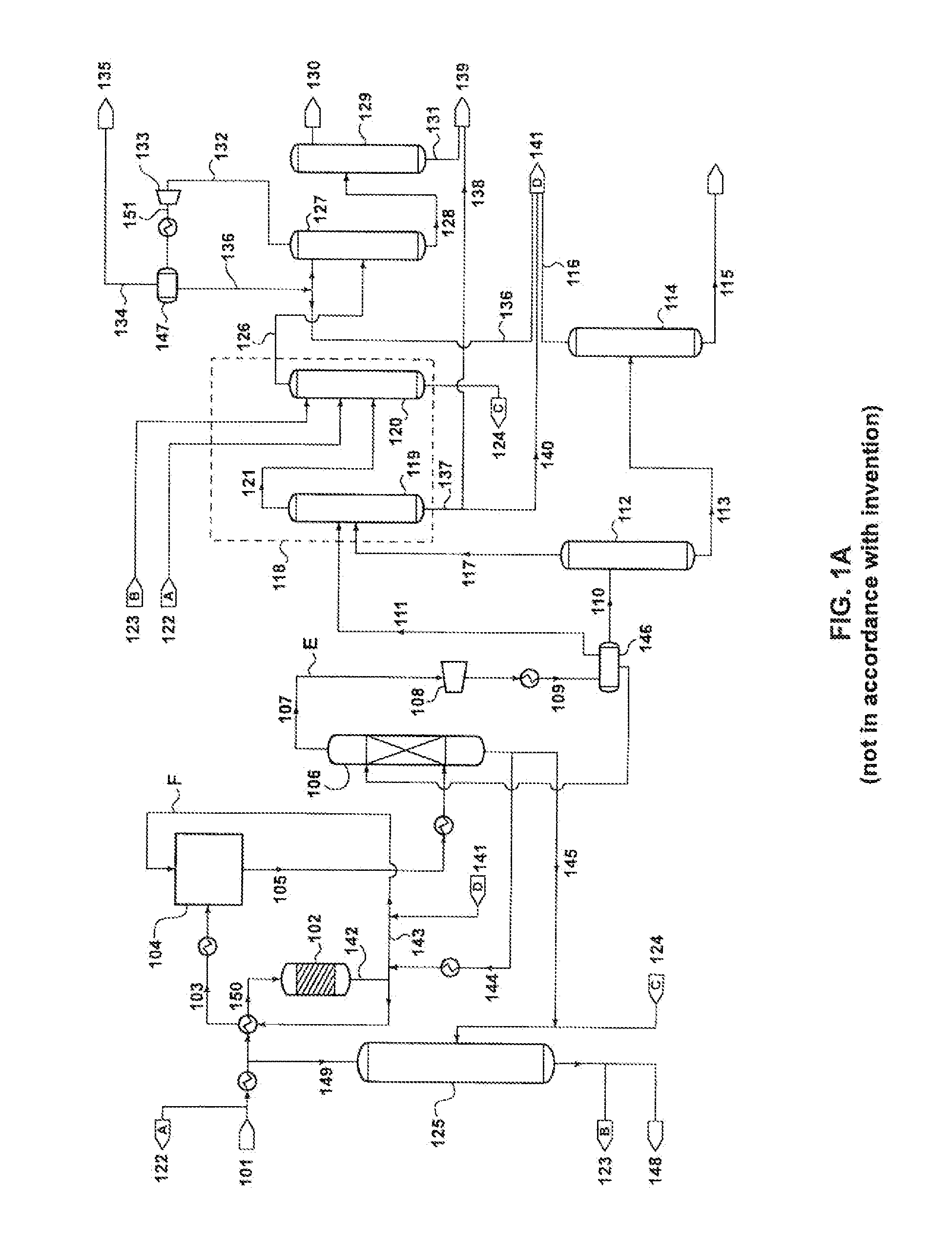
[0123]The following calculation was performed according to the process schematic illustrated in FIG. 1A, for a conventional MTP process. The plant was assumed to be processing 4,400 tons of methanol per day, and producing 1,370 tons of propylene per day.
[0124]As shown in FIG. 1A, the portion of the lights stream from the de-ethanizer overhead that is to be purged to the fuel line is sent first to compression, 133, cooling, and phase separation, 147, to separate out some of the ethylene in stream 136. Stream 135 is sent as purge to the fuel line. Results of the calculation are presented in Table 1.
[0125]
TABLE 1Conventional MTP Process (not in accordance with th...
example 2
Process of the Invention, with One Membrane Separation Step, and Recycle of C1 and C2 Hydrocarbons to the De-Ethanizer
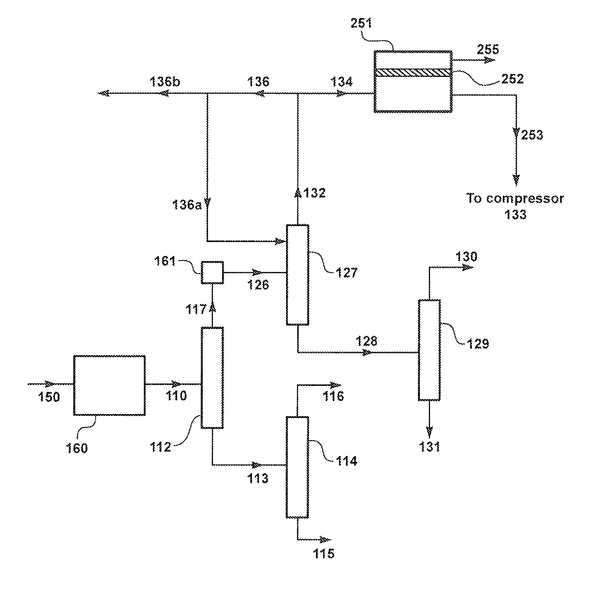
[0127]The following calculation was performed according to the process schematic illustrated in FIG. 2B, where a stream, 132, containing mostly inerts and C1 and C2 hydrocarbons is withdrawn from the top of the de-ethanizer column 127 and processed as feed stream 250 in membrane separation unit 251 containing membranes 252 that are selective to hydrogen over C1 and C2 hydrocarbons. Hydrocarbon-enriched membrane residue stream 253 is then combined with stream 132 and routed as combined stream 254 to the process upstream of compressor 133, from where it is passed as compressed stream 151 via condenser 147, and streams 136 and 141 to hydrocarbon recycle at position D.
[0128]The membrane 252 was assumed to have a hydrogen / ethylene selectivity of 14.3 and a hydrogen permeance of 672 gpu. Membrane area was assumed to be 76 m2. Results of the calculation are presented in Tab...
example 3
Process of the Invention, with Two Membrane Separation Steps and Recycle of C1 and C2 Hydrocarbons to Either the Compressor Downstream of the Quench Column or to the MTP Reactor
[0131]The following calculation was performed according to the process schematic illustrated in FIG. 4, where a stream 134 containing mostly inerts and C1 and C2 hydrocarbons is withdrawn from the top of the de-ethanizer column 127 and processed in a first membrane separation unit, 451, containing membranes, 452, that are selective to hydrogen over C1 and C2 hydrocarbons, followed by processing of the residue stream, 453, from the first membrane unit in a second membrane unit, 461, containing membranes, 462, that are selective to C1 and C2 hydrocarbons over hydrogen.
[0132]Hydrocarbon-enriched second membrane permeate stream 465 can then be recycled back to the process at one (or both) of two positions:[0133]To position E: After quench column 106 and upstream of main compressor 108.[0134]To position F: Directl...
PUM
| Property | Measurement | Unit |
|---|---|---|
| pressure | aaaaa | aaaaa |
| pressure | aaaaa | aaaaa |
| area | aaaaa | aaaaa |
Abstract
Description
Claims
Application Information