Apparatus for creating a vortex system

a technology of vortex system and apparatus, applied in the direction of centrifuges, separation processes, filtration separation, etc., can solve the problems of low success rate of magnetic field use in various applications, limited success rate of magnetic field use in industrial cooling towers, steam heaters, etc., and achieve the effect of greater reaction

Inactive Publication Date: 2015-12-15
KING BOBBIE
View PDF8 Cites 0 Cited by
  • Summary
  • Abstract
  • Description
  • Claims
  • Application Information

AI Technical Summary

Benefits of technology

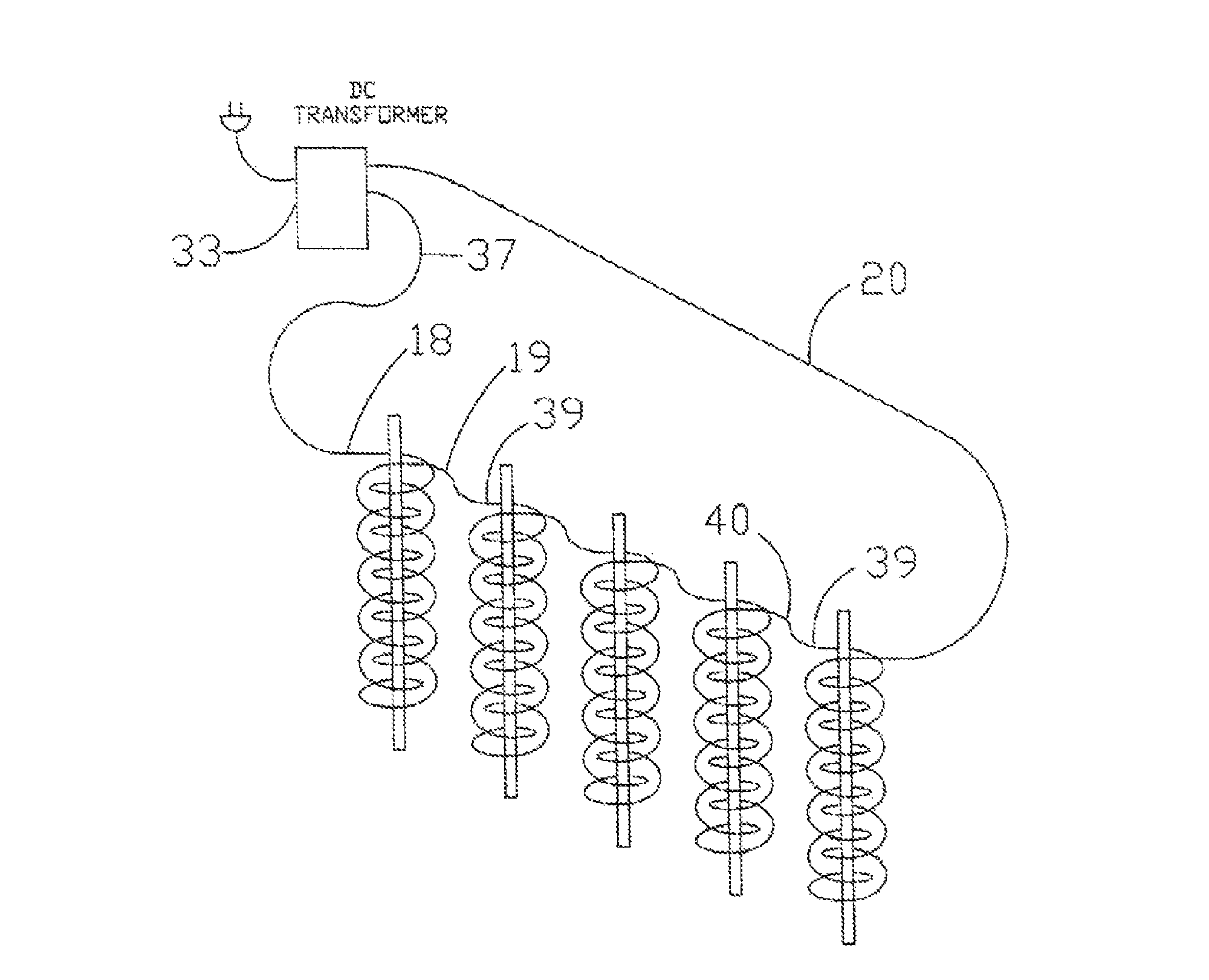
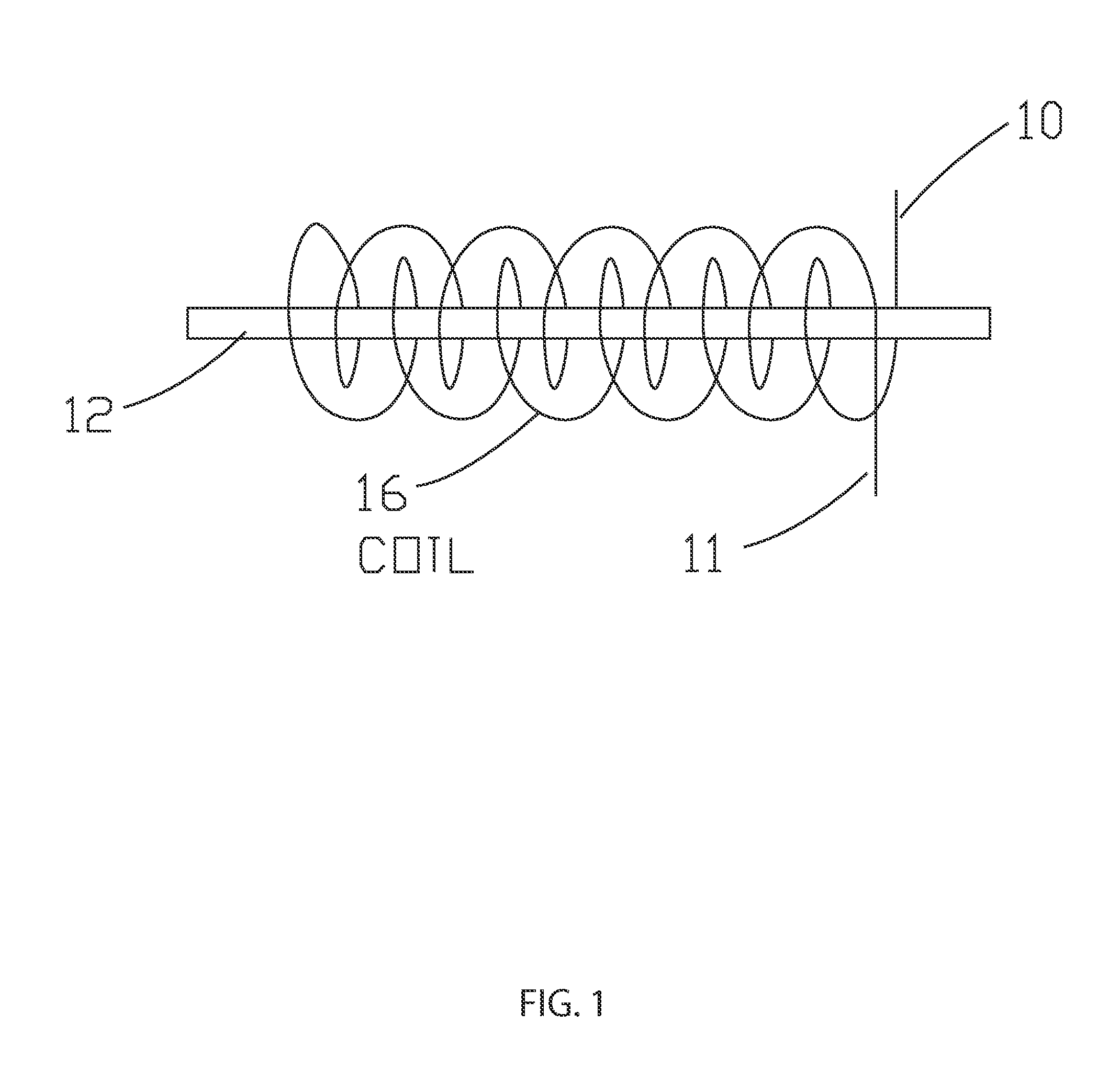
[0006]The bottom wire of the first rod is connected to a positive line (18) of a DC power supply; the top wire of the first rod (19) is connected to the bottom wire end of the adjacent rod; the last top wire (20) of the last rod is connected to the negative line of the DC power supply; the bottom end of the wire of the last rod is connected to the top end of the end of the adjacent rod (39); and each of the plurality of rods between the first rod and the last rod having the top and bottom ends of wire connected to the wire ends of each adjacent rod. Staggering the rods creates (FIG. 4) a vortex effect, which causes the field to crosscut the water many more times than the standard magnetic fields (FIG. 18) increasing the frequency (15) and magnetic (14) field. The staggering of the rods (FIG. 4) will increase the number of times the frequency (15) and the magnetic fields (14) will crosscut and react with the flowing liquid. This innovative process will cause a greater reaction within the flowing liquid that is being treated.

Problems solved by technology

Magnetic fields have been used in various applications, such as removal of scale buildup within a liquid environment with limited success.
The use of magnetic fields in industrial cooling towers, steam heaters, boilers, waste water treatment and water purification has had a very low success rate.

Method used


Image

  • Apparatus for creating a vortex system
  • Apparatus for creating a vortex system
  • Apparatus for creating a vortex system

Examples


example 1

[0055]A water boiling and steam temperature test was conducted. Identical glass pots, water source and amount of water were used. The stove is new and the heating elements are the same size. The temperature of the city water at a full boil was 210 degrees Fahrenheit. The temperature of the treated city water was 180 degrees Fahrenheit at a full boil. All conditions being equal, at a full boil the steam of the treated water was 10 degrees hotter than the city untreated water steam. The treated water created hotter steam; however the untreated city water boiled away twice as fast as the treated water. The test was repeated swapping pans and heating elements with the same results as previously observed.

example 2

[0056]Examples of industrial use in cooling towers shows a small Imeco cooling tower tied to a closed loop refrigeration system blowing down at one and one half cycles was using in excess of 22,000 gallons of water per year. At this setting a scale of approximately ½ inch thick on the bottom of the tower was observed even with the use of chemicals in the tower. The fill had a visible amount of calcium buildup on it. The apparatus was installed, all chemicals removed, and the cycle setting set fifteen After one month all of the buildup on both the bottom and fill disappeared. Also the bacteria count was reduced to less than 100 colony-forming units per milliliter (cfu / ml) as tested by an outside-certified lab. This is less than 1 / 100 of the Cooling Tower Institute maximum recommendation of 10,000 cfu / ml. After six months of operation and monthly bacteria test, the tower is still clean and bacteria counts are still minimal with no additional maintaince required. The water is clear, wi...

example 3

[0057]Examples of industrial use in cooling towers shows two BAC cooling towers tied to two Trane 125 Ton Chillers, blowing down at 2.3 cycles, using in excess of 4,000,000 gallons of water per year. At this setting a heavy scale on both the bottom and sides of the tower and on the fill was observed even with the use of chemicals in the tower.

[0058]Various plants and algae were growing on both the sides and on the top of the tower. Visible deterioration of metal components was evident due to the use of chemicals. The apparatus was installed, all chemicals removed, and the cycle setting adjusted from 2.3 to 5. After one month all scale and algae build up on both the bottom, sides and fill disappeared. The bacteria count was reduced to less than 100 colony-forming units per milliliter (cfu / ml) as tested by an outside certified lab. This is less than 1 / 100 of the acceptable Cooling Tower Institute maximum recommendation of 10,000 cfu / ml. After six months of operation and monthly bacter...


PUM

PropertyMeasurementUnit
lengthaaaaaaaaaa
lengthaaaaaaaaaa
lengthaaaaaaaaaa

Abstract

An apparatus delivering multi-vibrational, frequency-based, electromagnetic fields, which are independent but may work simultaneously. The apparatus may be used in many applications, especially in industrial applications such as cooling towers and related pipes and plumbing. The apparatus ELIMINATES calcium based hard water deposits and PROHIBITS bacteria build-up in cooling towers. The apparatus will help reduce soap usage in industrial laundry, reduce salt usage in water softeners, reduce chemical use in pools, inhibit algae growth and increase water clarity. The apparatus will restructure calcium carbonate and other mineral deposits to prevent mineral buildup. The apparatus may be formed from a plurality of wire-wrapped rods staggered around a pipe and connected to a power supply. The plurality of rods may be encased in flexible coating, wrapped in appropriate fabric, or encased in metal outer covering. As a result, waste water is reduced, water costs is kept low, and water is conserved.

Description

FIELD OF THE INVENTION[0001]The present invention relates generally to an apparatus that is a high performance, economical treatment created for industrial uses, especially, but not limited to, cooling towers, steam heaters, boilers, waste water treatment and water purification. Environmental requirements and mandates are changing and becoming extremely stringent. This new apparatus allows for affordable compliance. The apparatus offers a unique design that creates a high performance, staggered rod construction, based on a naturally occurring vortex system that intensifies the multiple vibrational and magnetic high frequency fields that may / can change the molecular structure of liquids, in particular water.BACKGROUND OF THE INVENTION[0002]While testing reactions related to Patent Pending Title: FUEL ADDITIVE APPARATUS, SYSTEM AND METHOD (US patent publication 20100236938A1) a coated copper wire was wrapped in a coil configuration on a steel rod. This coated copper wire wrapped aroun...

Claims


Application Information

Patent Timeline
Patent Type & Authority Patents(United States)
IPC IPC(8): C02F1/48C02F1/50
CPCC02F1/485C02F1/505C02F2201/483C02F2303/04C02F2303/22
Inventor BRAUGHT, LYNELL
Owner KING BOBBIE
Why Eureka
Try Eureka