
Pump or rotary cutter for operation in a fluid

Active Publication Date: 2015-12-22
ECP ENTWICKLUNGSGMBH
View PDF245 Cites 56 Cited by
  • Summary
  • Abstract
  • Description
  • Claims
  • Application Information

AI Technical Summary

Benefits of technology

The patent describes a method for creating a material that can change from a liquid state to a solid state through a chemical reaction. This material can be used in various applications, such as in a conveying element of a fluid pump or a bracing element of a rotary cutter. By using a specific type of polyol and a specific chain length, the material can have lower stiffness or viscosity in its transport state than in its operating state, making it easier to compress and deform. This allows for easier handling and reduced costs during transportation and assembly. The use of polyester polyols also improves stability and makes the material more durable. Overall, this patent describes a technique for creating a flexible, easy-to-compress material that can be used in various applications.

Problems solved by technology

In this respect, it is difficult to introduce these devices through the body's own vessels since the corresponding dimensions have to be kept very small for this purpose, with simultaneously larger dimensions being sensible in operation for the efficiency of use.
For this purpose, complex and / or expensive mechanical constructions are known which serve the erection of conveying elements of a rotor.
In addition, it is often necessary to stabilize the corresponding conveying elements such as conveying blades in operation since they are exposed to considerable fluid forces in operation.
In this respect, there is as a rule the problem that, on the one hand, the construction and the materials of the rotor should be stable in operation in order reliably to convey the fluid at high speeds and that, on the other hand, a certain yielding of at least parts of the rotor is desirable to keep the forces which are necessary for the compression of the rotor or of the pump within limits.

Method used


Image

  • Pump or rotary cutter for operation in a fluid
  • Pump or rotary cutter for operation in a fluid
  • Pump or rotary cutter for operation in a fluid

Examples


Embodiment Construction

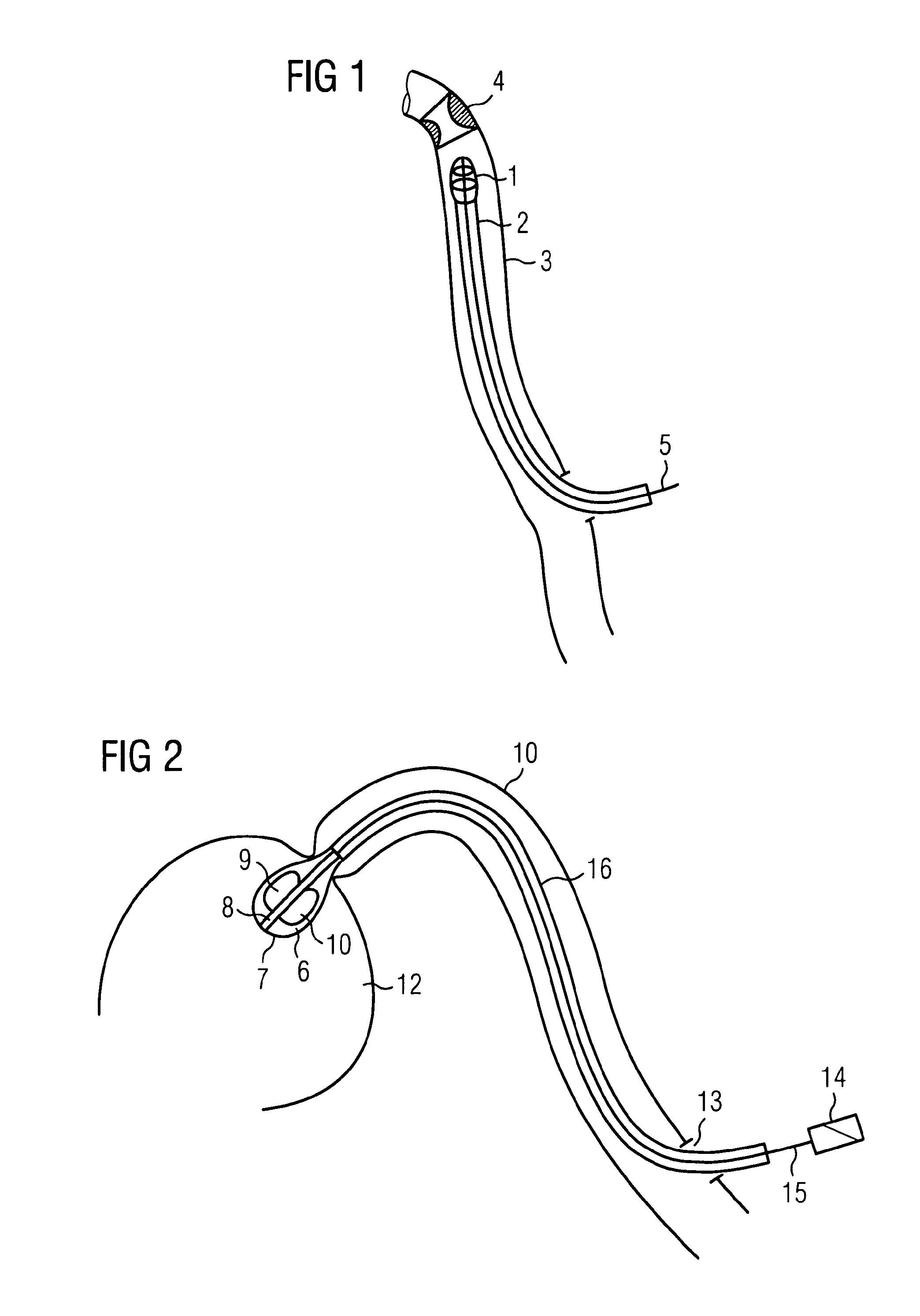
[0128]FIG. 1 shows, as an example for an apparatus in accordance with the invention, a rotary cutter 1 which is introduced at the distal end of a hollow catheter 2 into a blood vessel 3 of a human body to eliminate a constriction 4 by cutting away deposits at the wall of the blood vessel. A shaft 5 runs within the hollow catheter 2, said shaft being configured for a rotation at high speed and being able to be driven by a motor from outside the hollow catheter.

[0129]The rotary cutter 1 is advantageously first introduced into the blood vessel 3 in a transport state, for example in radially compressed form, and is then changed into an operating state on site which can, for example, differ from the transport state in that the cutter head is radially enlarged or stiffened. The invention solves the problem of effecting this change in the mechanical properties of the rotary cutter in a favorable form after passing through the transport path.

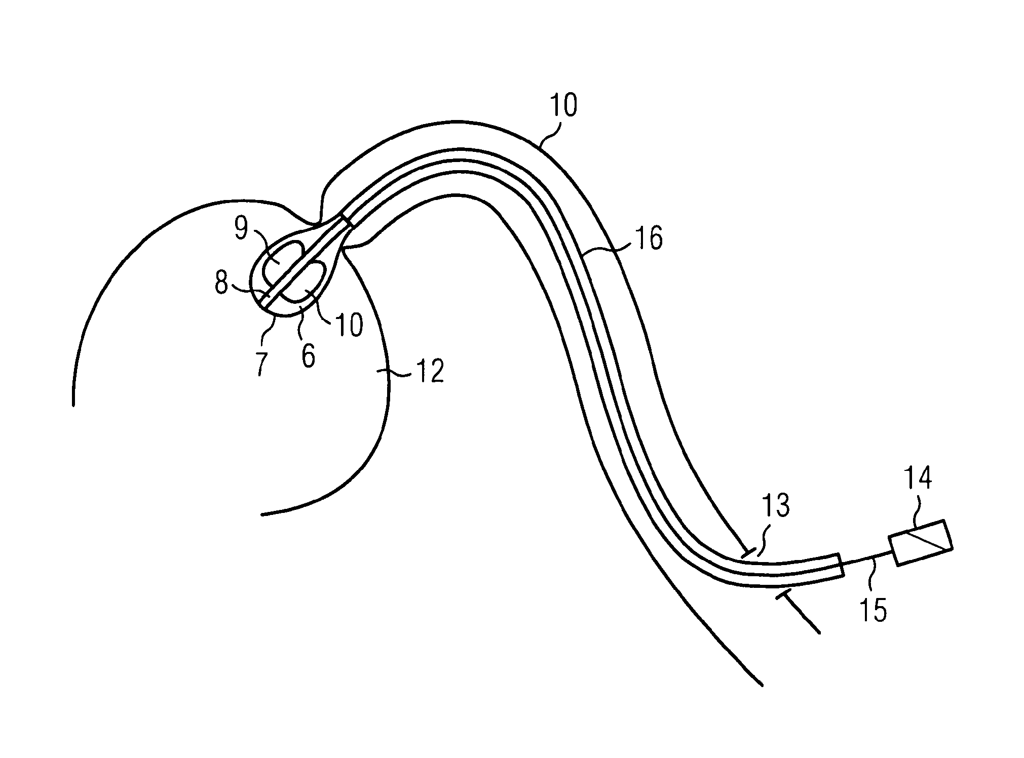
[0130]FIG. 2 shows a further example application ...


PUM


Abstract

The invention relates to a fluid pump or rotary cutter having at least one first element which can be brought from a transport state into an operating state by changing at least one mechanical property. Such a pump can, for example, be a blood pump for the medical, microinvasive area. The object of achieving a transition between the transport state and the operating state which is as comfortable as possible and in so doing leaving a freedom in the design of the corresponding apparatus, in particular of a pump, which is as large as possible, is achieved using the means of the invention in that the first element at least partly comprises a material or can be filled with a material or material mixture which passes through a chemical reaction, in particular cross-linking, or a crystallization for transition into the operating state.

Description

BACKGROUND OF THE INVENTION[0001]The invention is in the field of mechanical engineering and precision engineering and can be used to particular advantage in apparatus which are conveyed to a deployment site in a transport state and are there brought into an operating state before they are started.[0002]This is, for example, sensible with devices which have to be conveyed to sites which are difficult to access in order to be used there, for example pumps or machining tools in contorted hose systems or pipe systems.[0003]In the microscopic scale, such devices can be used as microinvasive devices, for example pumps or rotary cutters in human or animal vessels, for example blood vessels or other bodily cavities.[0004]In this respect, it is difficult to introduce these devices through the body's own vessels since the corresponding dimensions have to be kept very small for this purpose, with simultaneously larger dimensions being sensible in operation for the efficiency of use.[0005]In t...

Claims


Application Information

Patent Timeline
IPC IPC(8): A61M1/10F04D3/00F04D29/24A61B17/3207A61M1/12A61M60/135A61M60/178A61M60/216A61M60/462
CPCF04D29/247A61B17/320725A61B17/320758F04D3/00A61M1/1024A61M1/125A61M1/101A61M60/414A61M60/135A61M60/148A61M60/216A61M60/178A61M60/462A61M2205/0277A61M2205/0288F04D29/24
Inventor WIESSLER, PETRAFRIEDEL, SVEN-RENELIEBING, REINERER, SAMISCHLICHT, HENNING
Owner ECP ENTWICKLUNGSGMBH
Learn More