Solid oxide cell stack and method for preparing same

a solid oxide cell and stack structure technology, applied in the direction of cell components, electrochemical generators, coatings, etc., can solve the problems of reducing the performance of the solid oxide cell stack structure, reducing the beneficial effect of the catalyst in the electrodes, and reducing the catalytic activity in the electrodes of the stack structure over time, so as to achieve less sensitive, simple, elegant and rather inexpensive, the effect of simple and simple procedur

Active Publication Date: 2016-02-23
HALDOR TOPSOE AS +1
View PDF5 Cites 0 Cited by
  • Summary
  • Abstract
  • Description
  • Claims
  • Application Information

AI Technical Summary

Benefits of technology

[0030]Another advantage of the present invention is that the amount of catalyst deposited in the electrodes and the overall catalyst dispersion in the electrodes both are less sensitive to the impregnation procedure. Hence, in connection with one or more of the above and below embodiments the invention also encompasses impregnating the catalyst precursor by means of pouring or pumping a solution of the catalyst precursor through the manifolds of the stack. This pouring or pumping involves flushing the solution, preferably an aqueous solution, through the manifolds of the stack and represents a simple, straightforward, elegant and rather inexpensive way of providing the catalyst to the electrodes compared to other suitable, yet much more complicated impregnation methods such as pressure filtration. More preferably the impregnation is conducted by pumping the solution of catalyst through pipes adapted to any of the manifolds of the solid oxide cell stack structure. This represents an even easier and more simple procedure than pouring. The material chosen for impregnation, such as a salt of the catalytically active component, is preferably dissolved in aqueous solution and the solution is sent via the internal or external manifold through the stack on the cathode or anode side (or both), depending on which side of the cells is to be impregnated. Organic solutions, suspensions of particles, melts and aerosols can also be used. The cells become wet on one or both sides and the salt is deposited by drying, thus leaving small particles with a high catalytic effect on the electrode. The form and composition of the particles may change during the subsequent heating to the temperature of operation due to decomposition of the precursors and formation of more stable oxide particles. The process of achieving a good dispersion of the suspension or precursor solution in the electrode structure is assisted by placing the stack in vacuum prior to drying and optionally by adding suitable surfactants to the solution. Accordingly, in connection with one or more of the above and below embodiments, the invention also encompasses providing a vacuum to the stack prior to the drying step. The vacuum is provided in the stack by e.g. connecting a vacuum pump to the manifold volume or by placing the stack in a vacuum chamber, preferably for up to 12 hrs prior to the drying step.
[0031]The stack can now be operated as usual, but with a reduced area specific resistance (ASR) and thereby an improved performance due to the deposited particles.
[0032]It is to be understood that the term “drying” as used herein defines removal of water or any other solvent utilised in the solution of the catalyst precursor.
[0033]Yet another advantage is that the catalyst can be deposited properly by simple drying procedures. Hence, in connection with one or more of the above and below embodiments the invention encompasses drying the solution of the catalytic precursor by blowing air through the stack or heating the stack at 100° C. or higher (calcination). For instance, air at 100° C. or 200° C. can be blown through the stack or the stack may simply be put in a furnace at 100° C. or 200° C. or higher. The desired oxide of the catalytic precursor material is formed during the drying step or in the subsequent heating of the stack to the operating temperature.
[0034]The catalyst precursor is preferably selected from the group consisting of Ni, Ni—Fe alloy, ceria, doped ceria, zirconia, doped zirconia, MasTi1-x MbxO3-δ with Ma=Ba, Sr, Ca; Mb=V, Nb, Ta, Mo, W, Th, U; 0≦s≦0.5; LnCr1-xMxO3-δ, where Ln is an element of the lanthanide series and M=Ti, V, Mn, Nb, Mo, W, Th, U, Pr2O3 and AEZr1-x-y-zCexYyYbzO3, where AE=Ba, Sr, Ca; and mixtures thereof. These materials are suitable where the electrode for impregnation is the SOFC anode.
[0035]Where the electrode for impregnation is the SOFC cathode, the catalyst precursor is preferably selected from the group consisting of LSM (La1-xSrx)MnO3-δ, (Ln1-xSrx)MnO3-δ, (Ln1-xSrx)Fe1-yCoyO3-δ, (Y1-xCax) Fe1-yCoyO3-δ, (Gd1-xSrx)Fe1-yCoyO3-δ, (Gd1-xCax)Fe1-yCoyO3-δ, (Y, Ca) Fe1-yCoyO3-δ, ceria, doped ceria, zirconia, doped zirconia, La(Ni,Fe)O3, La(Ni,Co)O3, La2NiO4, Ln1-xAE2xTmO4, where TM is a transition metal, Ln is a lanthanide element, and AE is an alkali earth element, Pr2O3; and mixtures thereof. δ is a number for the oxygen deficiency in the lattice and is dependent on composition and the actual oxygen partial pressure pO2 (as pO2 decreasomg, δ increases). The number is usually between 0 and 0.3.

Problems solved by technology

However, it has been found that the beneficial effect of the catalyst in the electrodes is partly or fully lost upon heating the cells above 800° C. during stack assembling and initiation.
Moreover, when subsequently put into operation, the catalytic activity in the electrodes of the stack structure is reduced over time due to for instance nickel agglomeration or sintering in the anodes or cathode degradation because of instability towards decomposition and impurities.
This results in an overall decrease in the performance of the solid oxide cell stack structure.
Such loss of performance can bring the stack structure outside the required specifications within a given application, for instance in SOFC stack structures used in power producing units, thus forcing their replacement.
This is cost-intensive and deterring when considering the commercial prospects of using solid oxide cell technology.

Method used


Image

  • Solid oxide cell stack and method for preparing same
  • Solid oxide cell stack and method for preparing same
  • Solid oxide cell stack and method for preparing same

Examples


example 1

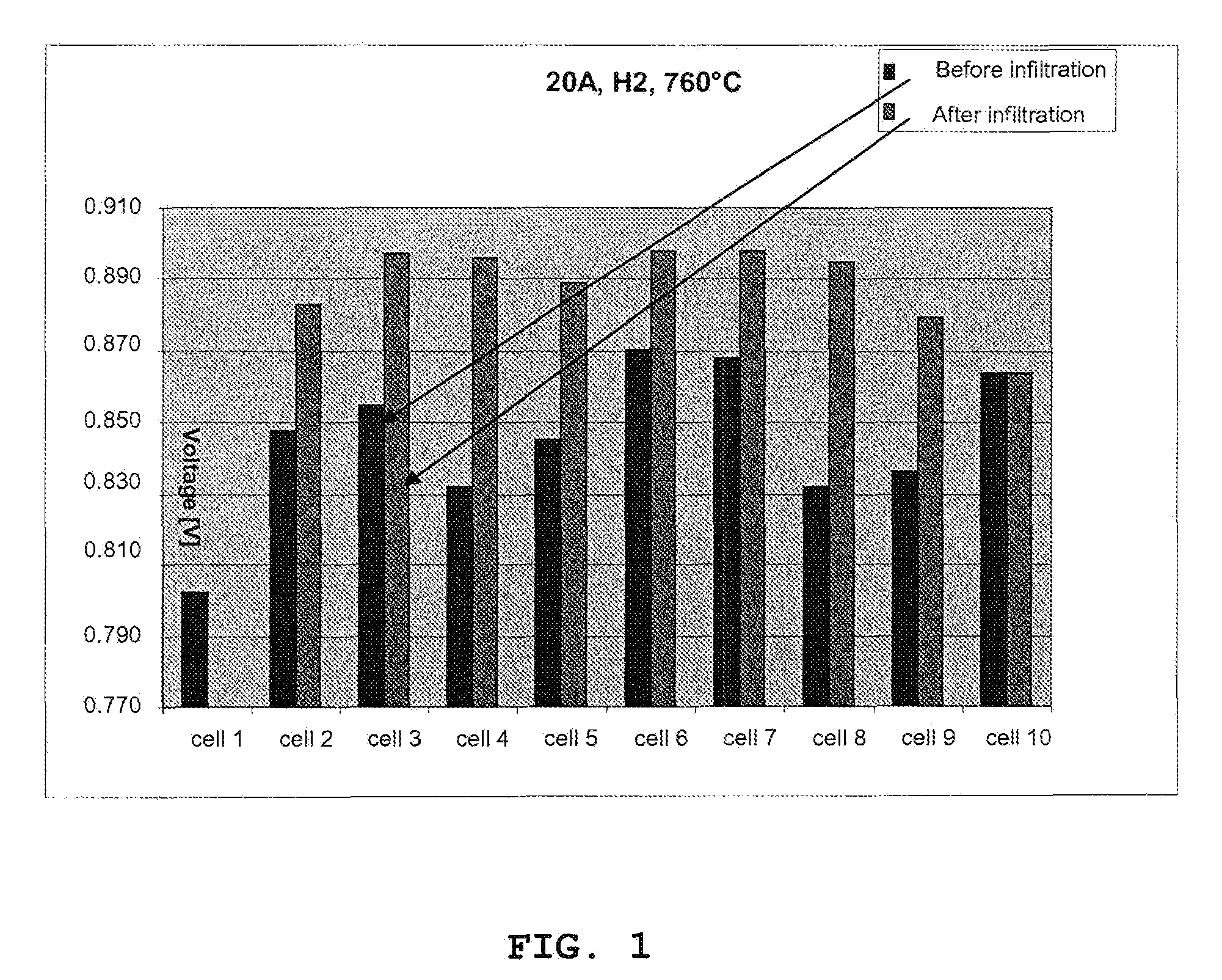
[0058]This example shows the performance in terms of voltage improvement of a solid oxide fuel cell structure at 760° C. The structure contains ten single cells and is prepared according to the invention where the cathode of the single solid oxide cells has been impregnated with a catalyst precursor after the stack has been assembled and initiated. The electrode layers of the single solid oxide cells have not been impregnated with a catalyst precursor before the stack is assembled and initiated, but contain the active material already in form of an Ni / YSZ anode and an LSM / YSZ cathode. In other words, the electrodes are already active.

[0059]After the assembling and the initiation (anode reduction), the cathode is impregnated with catalytic material (79% CeO2, 21% GdO11 / 2).

[0060]Appropriate amounts of the nitrate salts (here Ce-nitrate and Gd-nitrate) are dissolved in deionized water. A suitable surfactant (e.g. P123) is added with stirring. For the specific case the concentration was...

example 2

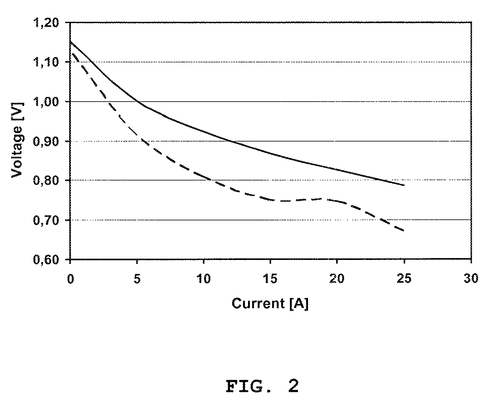
[0064]This example shows the performance in terms of voltage improvement of a solid oxide fuel cell structure at 680° C. The structure contains 10 single cells and is prepared according to the invention where the cathode of the single solid oxide cells has been impregnated with a catalyst precursor after the stack has been assembled and initiated. The electrode layers of the single solid oxide cells have not been impregnated with a catalyst precursor before the stack is assembled and initiated, but contain the active material already in form of an Ni / YSZ anode and an LSM / YSZ cathode. In other words, the electrodes are already active.

[0065]After the assembling and the initiation (anode reduction), the cathode is impregnated with catalytic material (79% CeO2, 21% GdO11 / 2).

[0066]The performance was measured in terms of voltage improvement of the cells of the stack at 0.22 A / cm2 and 680° C. In the anode: H2=150 l / h+N2=100 l / h and in the cathode air=960 l / h. FIG. 2 shows the voltage impr...

example 3

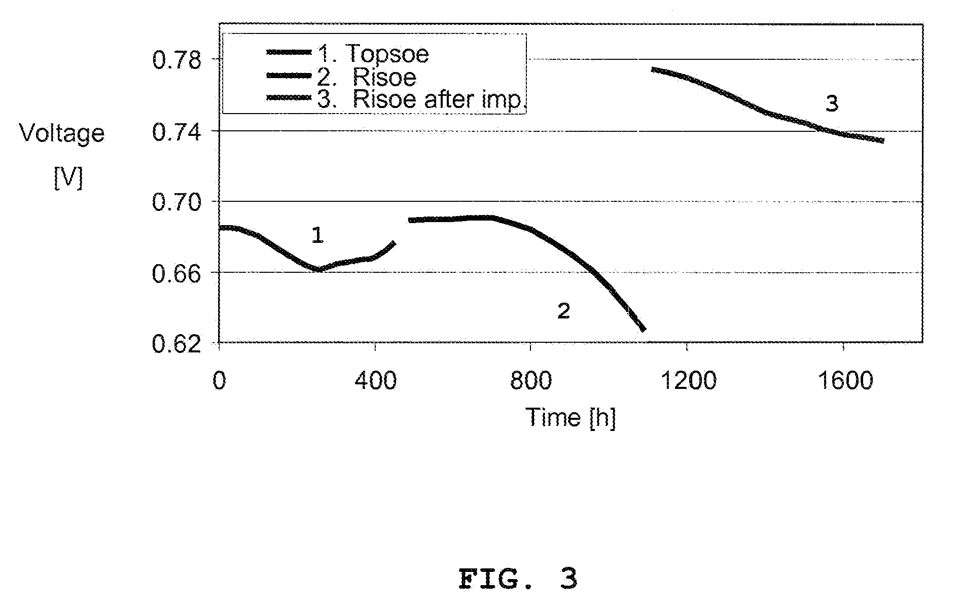
[0067]A 10 cell 12×12 cm stack based on anode supported cells with Ni / YSZ anodes and LSM / YSZ cathodes was assembled according to usual procedures. Some of the cells had been impregnated with a CGO precursors prior to the stack assembling right after the cathode firing. The electrical performance of these cells was indistinguishable from the electrical performance of those cells not impregnated. The stack was operated at ˜700° C. under a current load of 25 A while feeding 150 l / h H2 to the anode compartment. After about 400 hrs of operation, the stack operation was terminated and the stack cooled. After ˜30 days of storage under ambient conditions the stack was brought into operation again, but this time at a new site in a different laboratory. The initial performance was close to the one observed during the first test period, but after ˜100 hrs of operation the electrical performance of several cells started to degrade. After 1100 hrs of operation the stack was cooled down, and the ...


PUM

PropertyMeasurementUnit
temperaturesaaaaaaaaaa
particle diameteraaaaaaaaaa

Abstract

A method for producing and reactivating a solid oxide cell stack structure by providing a catalyst precursor in at least one of the electrode layers by impregnation and subsequent drying after the stack has been assembled and initiated. The method includes impregnating a catalyst precursor into a cathode of a solid oxide cell stack which already contains an active material (an anode reduction) for example, in the form of Ni/YSZ anodes. Due to a significantly improved performance and an unexpected voltage improvement this solid oxide cell stack structure is particularly suitable for use in solid oxide fuel cell (SOFC) and solid oxide electrolysing cell (SOEC) applications.

Description

BACKGROUND OF THE INVENTION[0001]1. Field of the Invention[0002]The present invention relates to a solid oxide cell stack structure and a method for preparing same. In particular the invention relates to a method for producing a novel solid oxide cell stack structure by providing a catalyst precursor in the electrode layers after the stack has been assembled and initiated. The invention relates also to a method for reactivation of a solid oxide cell stack structure that has degraded during operation. The solid oxide cell stack structure is particularly suitable for use in solid oxide fuel cell (SOFC) and solid oxide electrolysing cell (SOEC) applications.[0003]2. Description of the Related Art[0004]Solid oxide cell (SOC) is the generic term for specific types of electrochemical cells, particularly solid oxide fuel cells (SOFC) and solid oxide electrolysing cells (SOEC) which in either case contain a solid electrolyte layer arranged in between two electrodes. One electrode acts as ca...

Claims


Application Information

Patent Timeline
Patent Type & Authority Patents(United States)
IPC IPC(8): H01M4/88H01M8/24H01M4/90C25B9/00H01M8/12
CPCH01M4/8846C25B9/00H01M4/9016H01M8/2425H01M2008/1293Y02E60/50Y02E60/525H01M8/2404H01M8/2432
Inventor HENDRIKSEN, PETER VANGMIKKELSEN, LARSSOGAARD, MARTINHOGH, JENS VALDEMAR THORVALDKIEBACH, WOLFF-RAGNARJENSEN, KRESTEN J. N. L.
Owner HALDOR TOPSOE AS
Why Eureka
Try Eureka