Automatic enhanced self-driven synchronous rectification for power converters

a technology of power converters and synchronization corrections, applied in the field of power converters, can solve problems such as unipolar character of transformer core excitation, certain performance tradeoffs, and the need to reset the transformer cor

Active Publication Date: 2016-03-22
CRANE ELECTRONICS INC
View PDF173 Cites 19 Cited by
  • Summary
  • Abstract
  • Description
  • Claims
  • Application Information

AI Technical Summary

Problems solved by technology

These constraints require certain performance tradeoffs.
A limitation of forward converters is that it may be necessary to reset the transformer core to prevent saturation (i.e., discharge the magnetizing current of the transformer during the off period of the main switch).
This limitation results from the unipolar character of the transformer core excitation.
Nevertheless, this transformer resetting technique reduces the efficiency of the converter due to the dissipation of the magnetizing energy accumulated in the transformer during the on period of the switch.
The active-control methods like the one shown in FIG. 1 often require more complex circuit design and greater part counts, which may increase cost and product size.
Such synchronization may require an isolated feedback, which may require many more components and an increase in footprint.
Self-driven rectification schemes such as that shown in FIG. 2 are frequently used to decrease design complexity, but they have several limitations.
For example, a design that requires an input voltage range ratio which is greater than 3.13 may be challenging, especially for a design which can scale the output voltages from 3.3 V to 15 V without extra transformer windings.
This limitation becomes more problematic as the input voltage range ratio increases beyond 3:1.
These conventional self-driven methods have several drawbacks, but such drawbacks are not limited to the gate drive voltages.
These two contradictory requirements between the forward and catch synchronous FETs make it difficult to achieve a wide input.
Zener diodes are typically used for this purpose but the power losses in them are not desirable since the primary purpose of synchronous rectification is to minimize losses in the secondary switches.
Unfortunately, the timing circuitries on the secondary side are dependent on the line and load variation, so that no single optimal timing values can be set to cover the entire input voltage and output load ranges.
Errors in the timings will potentially cause shoot through current and consequently may limit the operating frequency to at most 300 kHz.
A potential drawback of this is a shoot through current for a sudden stop in which both synchronous FETs are turned on at the same time continuously for ten or more cycles, essentially creating a short circuit across the output.

Method used


Image

  • Automatic enhanced self-driven synchronous rectification for power converters
  • Automatic enhanced self-driven synchronous rectification for power converters
  • Automatic enhanced self-driven synchronous rectification for power converters

Examples


Embodiment Construction

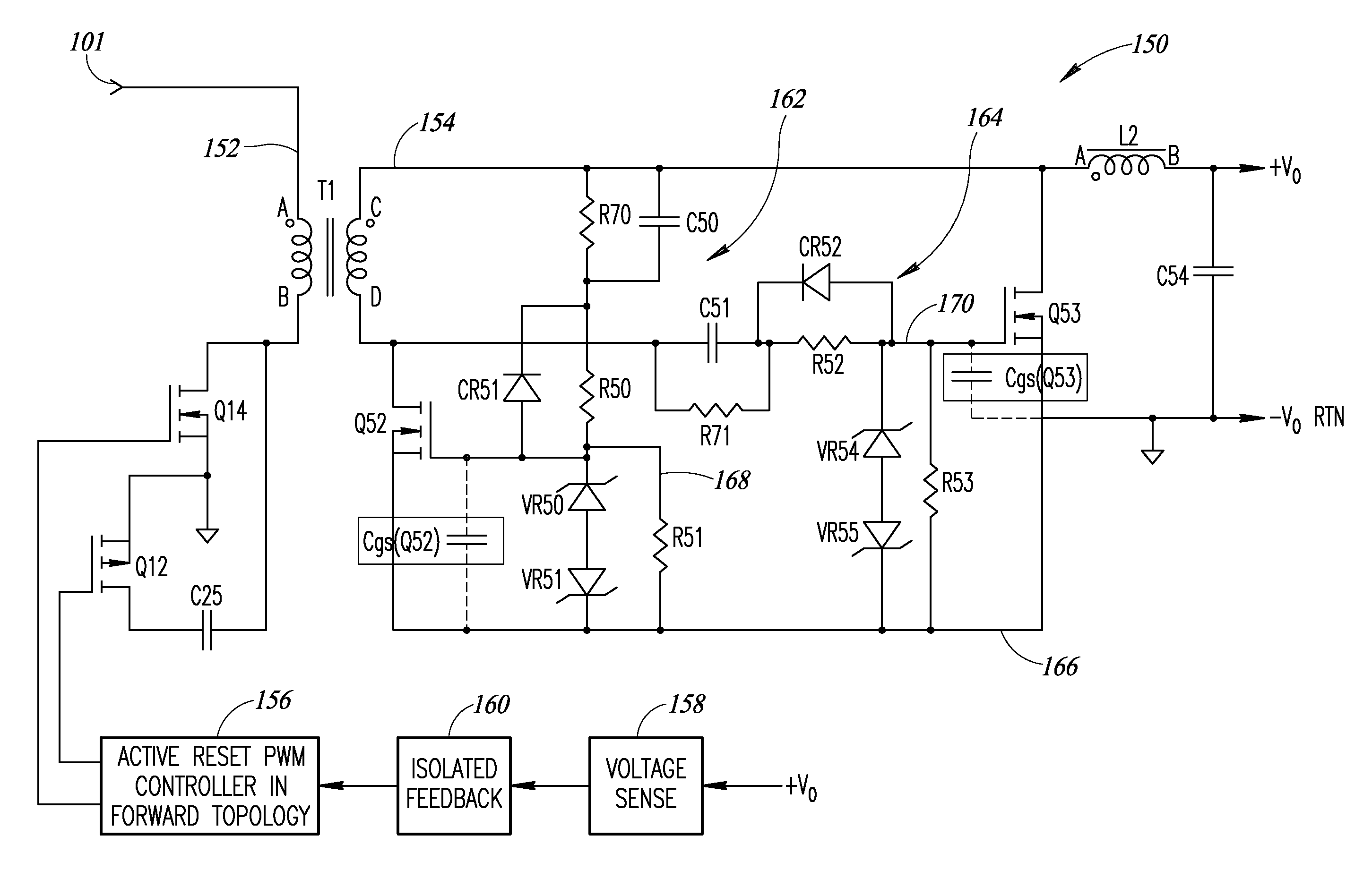
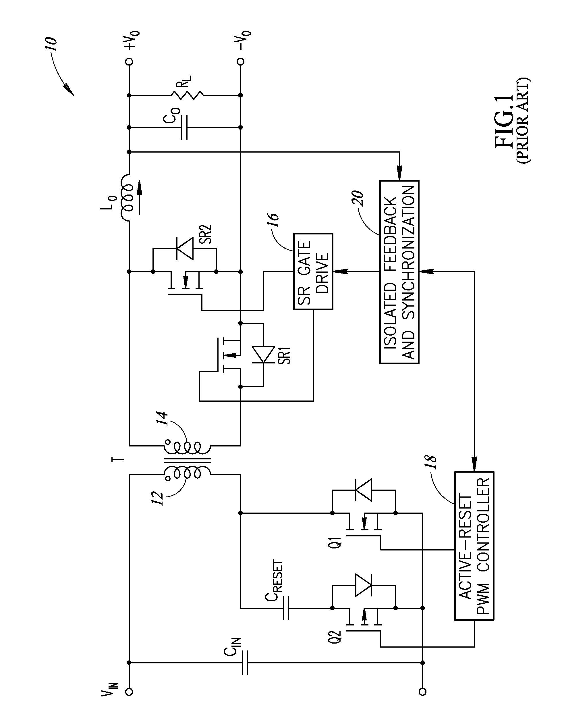
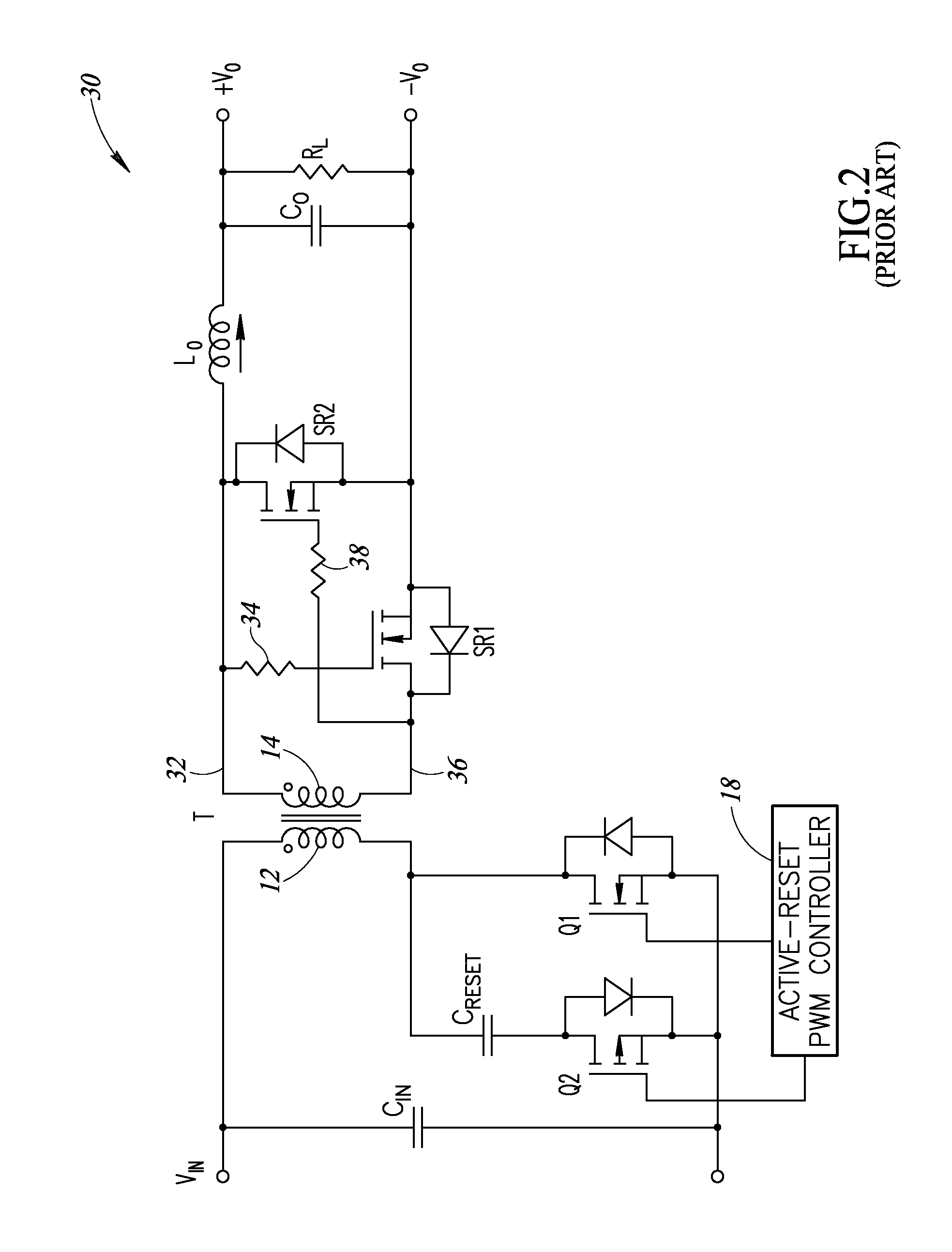
[0046]In the following description, certain specific details are set forth in order to provide a thorough understanding of various disclosed implementations. However, one skilled in the relevant art will recognize that implementations may be practiced without one or more of these specific details, or with other methods, components, materials, etc. In other instances, well-known structures associated with computer systems, server computers, and / or communications networks have not been shown or described in detail to avoid unnecessarily obscuring descriptions of the implementations.

[0047]Unless the context requires otherwise, throughout the specification and claims that follow, the word “comprising” is synonymous with “including,” and is inclusive or open-ended (i.e., does not exclude additional, unrecited elements or method acts).

[0048]Reference throughout this specification to “one implementation” or “an implementation” means that a particular feature, structure or characteristic de...


PUM


Abstract

Systems and methods for providing a self-driven synchronous rectification circuit for an active-clamp forward converter which includes automatically enhancing synchronous MOSFETs and maximizing input voltage range. The gate signals for the synchronous MOSFETs are derived from a unipolar magnetic coupling signal instead of a bipolarized magnetic coupling signal. The unipolar signal is retained for fully enhanced driving of the MOSFETs at low line voltage and the unipolar signal is automatically converted to a bipolar signal at high line amplitude due to line variance to maximize input voltage range by utilizing non-polarized characteristics of the MOSFET gate-to-source voltage (Vgs). The circuit permits efficient scaling for higher output voltages such as 12 volts DC or 15 volts DC, without requiring extra windings on the transformer of the forward converter.

Description

BACKGROUND[0001]1. Technical Field[0002]The present disclosure generally relates to power converters.[0003]2. Description of the Related Art[0004]DC / DC converters are a type of power supply which converts an input DC voltage to a different output DC voltage. Such converters typically include a transformer that is electrically coupled via a switching circuit between a voltage source and a load. Converters known as forward converters include a main switch connected between the voltage source and the primary winding of the transformer to provide forward power transfer to the secondary winding of the transformer when the switch is on and conducting. A metal oxide semiconductor field effect transistor (MOSFET) device is typically used for the switch.[0005]Power converter designs are often constrained by various requirements, such as efficiency, input voltage range, output voltage, power density, and footprint area. These constraints require certain performance tradeoffs. For instance, ac...

Claims


Application Information

Patent Timeline
Patent Type & Authority Patents(United States)
IPC IPC(8): H02M3/335
CPCH02M3/33546H02M3/33592H02M3/33576H02M3/33569H02M3/33523Y02B70/10
Inventor LAM, CUONSONG, SOVANNNGUYEN, KHOACHEN, HERMAN
Owner CRANE ELECTRONICS INC
Why Eureka
Try Eureka