Circuit, method and system for overload protection

a technology of overload protection and circuit, applied in transmission systems, power conversion systems, ac-dc network circuit arrangements, etc., can solve the problems of excessively high load current, power components of power supply damage, load not matching with power supply ratings, etc., to achieve moderate production costs and high reliability.

Active Publication Date: 2016-04-12
EFORE TELECOM FINLAND OY
View PDF12 Cites 0 Cited by
  • Summary
  • Abstract
  • Description
  • Claims
  • Application Information

AI Technical Summary

Benefits of technology

[0010]It is an object of the present invention to provide an overload protection circuit for various applications, wherein the described disadvantages of the prior art are avoided or reduced. The object of the invention is therefore to achieve overload protection which has high reliability, which can be implemented with moderate production cost, and which can be adapted for versatile requirements of power supplies and loads.
[0035]The present invention has substantial advantages over prior art solutions. The switching element of the circuit is not used for linear control of the current. Therefore, the power dissipation in the switching element is small. Also, the individual periods of power dissipation in the voltage dependent element are short. It is therefore feasible to provide an overload protection circuit in which power components operate in safe operating area. As a consequence, it is possible to achieve high reliability of the overload protection circuit as well as the power supply.
[0037]The overload circuit according to the present invention can be implemented with a small number of power components and control components, whereby the circuit can be economically produced.

Problems solved by technology

Such a high current may exceed the current output rating of the power supply, and this may cause power components of the power supply to get damaged.
Another cause for excessively high load current may be a short circuit or other fault in the load.
It is also possible that the load does not match with the power supply ratings.
These circuits limit and / or disconnect the current supplied to the load in situations where excessive current values are detected at the output of the power supply.
However, this solution of the prior art has a certain disadvantage. transistors cannot dissipate high power for long periods without exceeding safe operating area (SOA) of the transistor.
If the SOA of the transistor is exceeded there is a risk of the transistor becoming damaged.
The reliability of the device may thus be degraded.
As a further disadvantage, providing linear control of the switching transistor requires a more complicated structure of the control circuit.
There is also a potential risk of instability related to such a linear control.
There are certain disadvantages also concerning the prior art overload protection circuit according to FIG. 2.
Firstly, the load voltage does not reach the nominal value when the current is supplied through the resistor R1.
Secondly, the power resistor may dissipate a large amount of energy during the power start-up.
Such a power resistor has large dimensions and thus requires much space.
It is also a relatively expensive component, thus increasing the production cost of the device.
This further increases the complexity and production cost of the device.
Further, it is important that the reliability of the overload protection circuits is high because a failure may cause large part of an electronic system to become inoperative.
As described above, the overload protection circuits according to the prior art do not fulfil these requirements in a desirable manner.

Method used


Image

  • Circuit, method and system for overload protection
  • Circuit, method and system for overload protection
  • Circuit, method and system for overload protection

Examples


Embodiment Construction

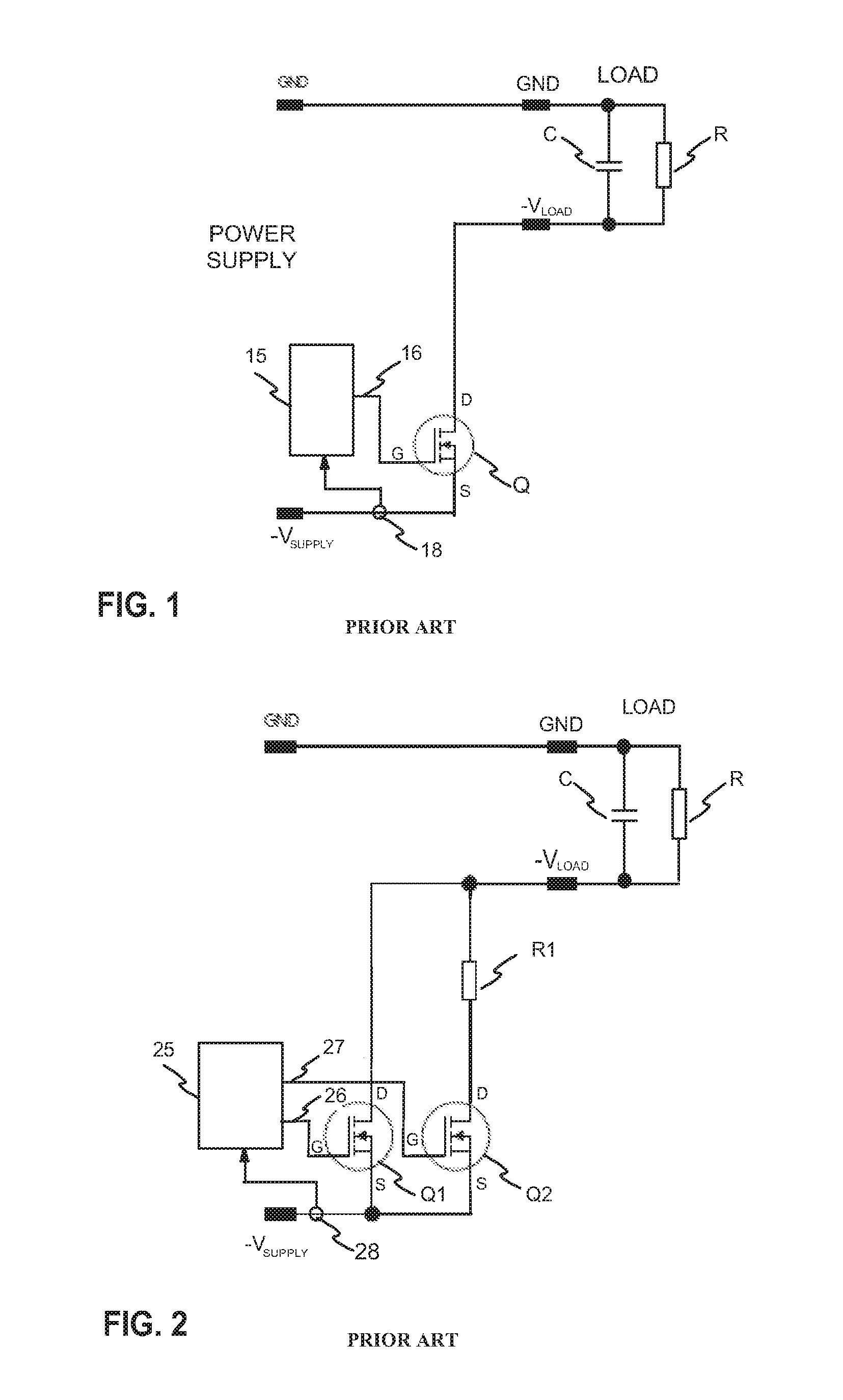
[0048]FIGS. 1 and 2 where described on the prior art part of the description.

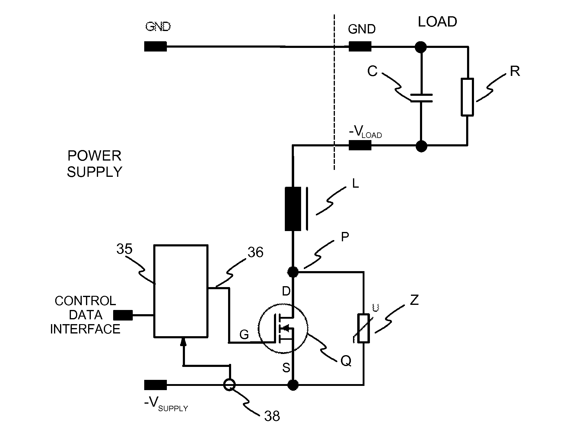
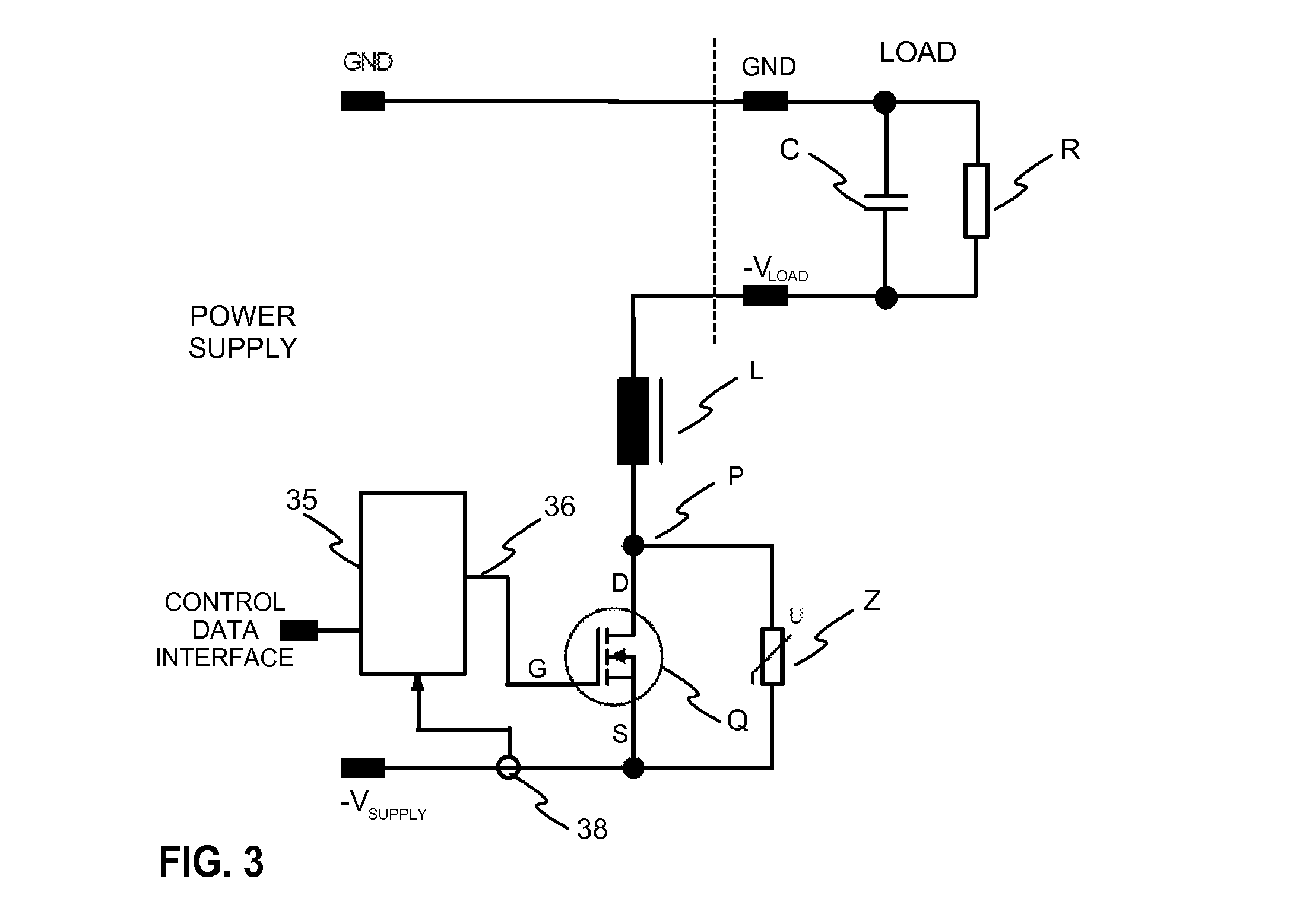
[0049]FIG. 3 illustrates an exemplary overload protection circuit according to the invention. A power supply provides an output voltage between ground GND and negative voltage output −VSUPPLY terminals. The power supply provides power to a load which has terminals for ground GND and negative voltage input −VLOAD. R is used in the Figure to denote resistive load and C is used to denote capacitive load.

[0050]The overload protection circuit has a switching element Q, which may be a power semiconductor, such as MOSFET or an IGBT, for example. The switching transistor is controlled with control means 35, which has a control output 36 connected to the gate G of the switching transistor. The overload protection circuit has an inductor L connected in series with the switching element Q. In the circuit of FIG. 3 the source S of the switching element is connected to the negative terminal −VSUPPLY of the power supply,...


PUM


Abstract

An overload protection circuit for supplying electric power has advantageous applications especially in supplying power to capacitive loads. In prior art circuits, the charging current is lead to the capacitive load through a linearly operating transistor or through a power resistor. Therefore, prior art circuits often involve a risk of exceeding safe operating area of a power transistor, or circuits with a large number of components are needed. The present overload protection circuit has an inductor (L) coupled in series with a switching element (Q). Load current is measured (35, 38), and the switching element (Q) is controlled (35, 36) to supply current to the load via the inductor (L) until a determined current limit is achieved. After achieving the current limit the switching element (Q) is controlled to off-state, during which the freewheeling current of the inductor (L) is lead through a voltage dependent element (Z).

Description

FIELD OF INVENTION[0001]The present invention relates generally to overload protection in supply of electric power. More specifically, the present invention relates to subject matter disclosed below and recited in the claims. The invention has advantageous applications especially in supplying power to capacitive loads.BACKGROUND[0002]Power supplies, such as switching power supplies, are used for providing direct current (DC) supply for various electronic devices, such as base stations in a cellular communications system. For a power supply, an electronic device is a load which often includes a capacitive load component. When power with a specified operating voltage is connected to such a load, a high current is initially formed for charging the capacitive load component. Such a high current may exceed the current output rating of the power supply, and this may cause power components of the power supply to get damaged. Another cause for excessively high load current may be a short ci...

Claims


Application Information

Patent Timeline
Patent Type & Authority Patents(United States)
IPC IPC(8): H02H9/02H02J4/00H02H9/00H02M1/00
CPCH02H9/025H02J4/00H02H9/001H02H9/02Y10T307/352H02H11/005H02H3/08H02H9/00
Inventor NISONEN, ILPO
Owner EFORE TELECOM FINLAND OY
Why Eureka
Try Eureka