Optical coupler and optical device including the same

a technology of optical couplers and optical couplers, applied in the field of optical couplers, can solve the problems of deteriorating optical coupling efficiency, requiring several centimeters (cm) of reverse taper length for low optical loss, and high optical loss ranging from about 10 db to about 20 db, and achieve the effect of minimizing optical loss

Active Publication Date: 2016-04-19
ELECTRONICS & TELECOMM RES INST
View PDF4 Cites 11 Cited by
  • Summary
  • Abstract
  • Description
  • Claims
  • Application Information

AI Technical Summary

Benefits of technology

[0006]The present invention provides an optical coupler capable of minimizing optical loss and an optical device including the same.
[0007]The present invention also provides an optical coupler capable of improving productivity and an optical device including the same.
[0008]Embodiments of the present invention provide optical couplers including: a substrate; a buffer layer on the substrate; and an optical coupling layer including a horizontal mode expander layer and a vertical mode expander layer, wherein the horizontal mode expander layer expands in one direction on the buffer layer, and wherein the vertical mode expander layer adjusts a stepped difference between the horizontal mode expander layer and a plurality of optical transmission devices having different diameters or sectional areas and connected to both sides of the horizontal mode expander layer, and the vertical mode expander layer is disposed on a side of the horizontal mode expander layer to minimize optical loss between the plurality of optical transmission devices.

Problems solved by technology

Direct connection of an optical waveguide and an optical fiber may lead to high optical loss reaching about 10 dB to about 20 dB.
However, when the second waveguide is coupled to a single-mode optical fiber, it requires several centimeters (cm) of a reverse taper length for low optical loss.
However, the optical fiber with the small core causes optical coupling efficiency to be deteriorated due to misalignment between an optical fiber and a waveguide, and also causes productivity to be lowered due to increase in optical module packaging costs.

Method used


Image

  • Optical coupler and optical device including the same
  • Optical coupler and optical device including the same
  • Optical coupler and optical device including the same

Examples


first embodiment

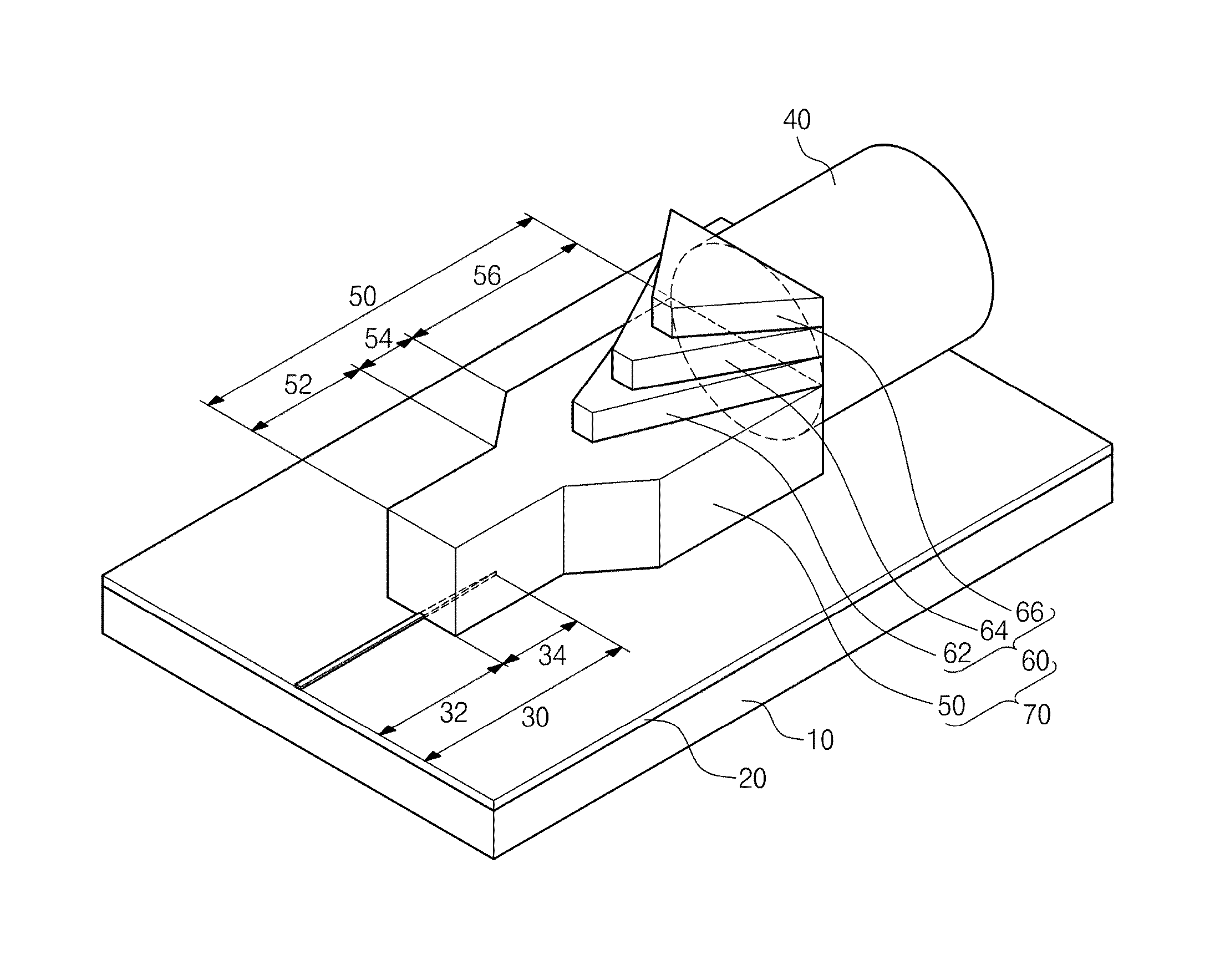
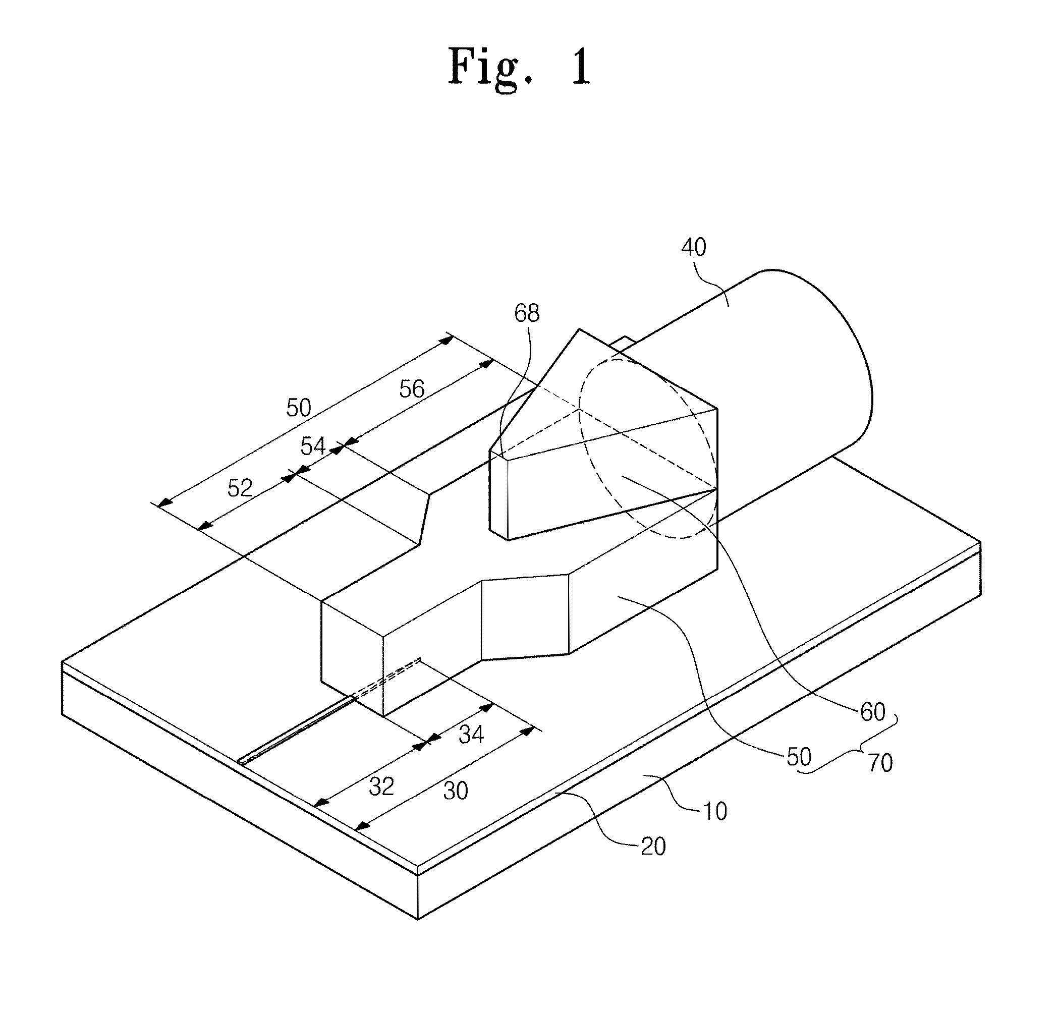
[0040]FIG. 1 is a perspective view illustrating an optical device according to the present invention.

[0041]Referring to FIG. 1, the optical device includes a substrate 10, a buffer layer 20, an optical waveguide 30, an optical fiber 40, and an optical coupler 70.

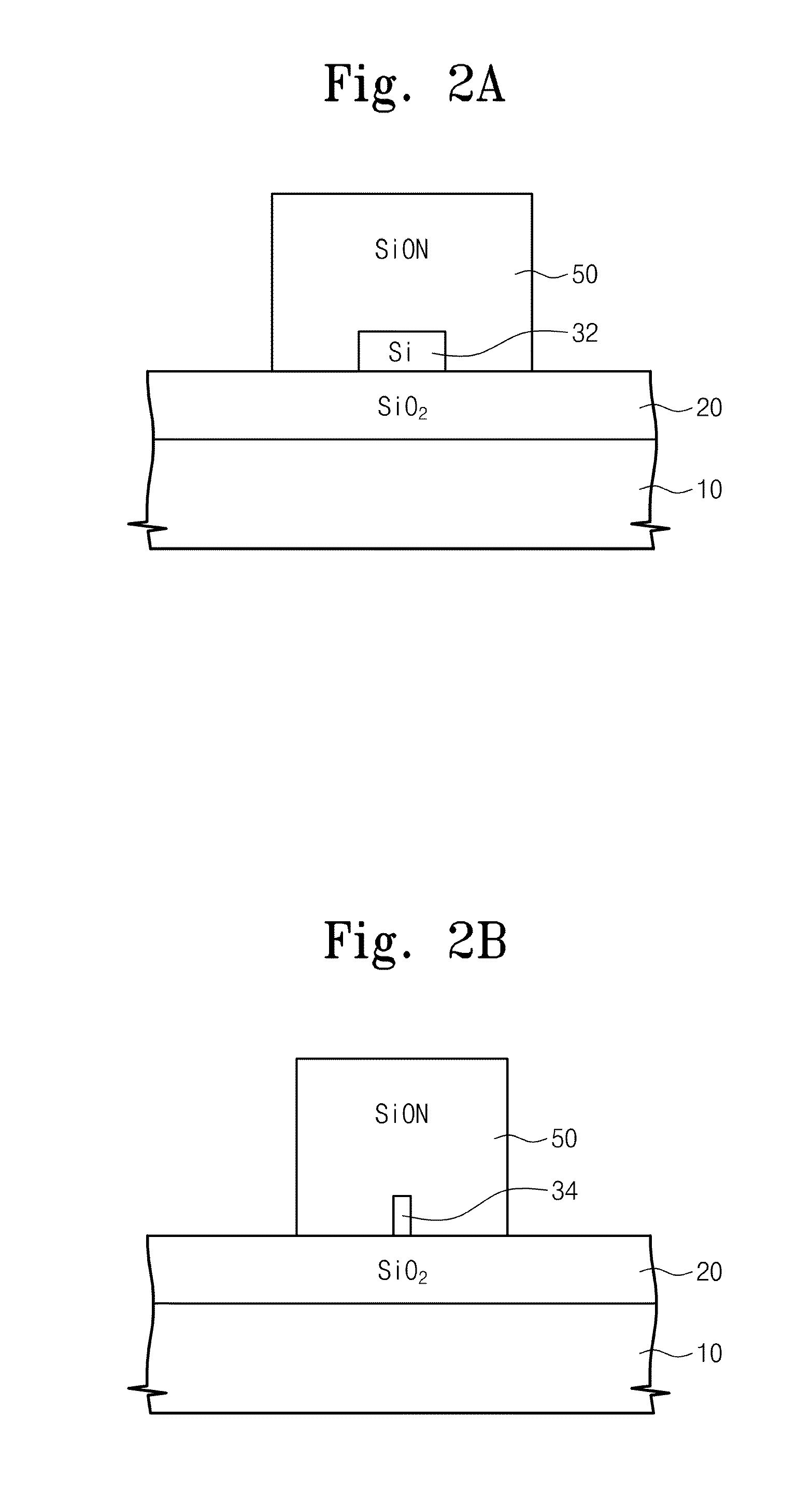
[0042]The substrate 10 may provide a flat surface. The buffer layer 20 may have a lower refractive index than the substrate 10. The substrate 10 may include a silicon wafer. The buffer layer 20 may include a silicon oxide layer having a lower refractive index than silicon. Silicon may have a refractive index of about 3.4. The silicon oxide layer may have a refractive index of about 1.45.

[0043]The optical waveguide 30 may be disposed on one side of the buffer layer 20 in one direction. The optical waveguide 30 may include crystalline silicon, polycrystalline silicon, or amorphous silicon, each of which has a higher refractive index than the buffer layer 20. The present invention is not limited thereto and thus various modific...

second embodiment

[0058]FIG. 6 is a perspective view illustrating an optical device according to a

[0059]Referring to FIG. 6, the optical device may include an optical coupler 70 including a plurality of vertical mode expander layers 60 having a stair structure. The vertical mode expander layers 60 include a first vertical mode expander layer 62, a second vertical mode expander layer, and a third vertical mode expander layer 68. The second vertical mode expander layer 64 may be shorter than the first vertical mode expander layer 62. The third vertical mode expander layer 68 may be shorter than the second vertical mode expander layer 64. In the second embodiment of the present invention, the vertical mode expander layer 60 of the optical coupler 70 in the first embodiment of the present invention is modified such that it includes the first to third vertical mode expander layers 62, 64, and 66 that are stacked in a plurality of step forms.

third embodiment

[0060]FIG. 7 is a perspective view illustrating an optical device according to the present invention.

[0061]Referring to FIG. 7, the optical device includes an optical coupler 70 including a vertical mode expander layer 60. The vertical mode expander layer 60 may be inclined to have its thickness that is increased as being progressively closer to the optical fiber 40. The tilt angle may be inversely proportional to the lengths of the vertical mode expander layer 60 and the vertical expander region 56. In the third embodiment of the present invention, the horizontal mode expander layer 60 in the first embodiment is modified such that it is inclined to have a thickness that is increased gradually in a direction from the optical waveguide 30 to the optical fiber 40.

[0062]According to embodiments of the present invention, an optical coupler may include a horizontal mode expander layer and a vertical mode expander layer. The horizontal mode expander layer may extend in one direction. The ...


PUM


Abstract

Provided are an optical coupler and an optical device including the same. The optical coupler includes: a substrate; a buffer layer on the substrate; and an optical coupling layer including a horizontal mode expander layer and a vertical mode expander layer, wherein the horizontal mode expander layer expands in one direction on the buffer layer, and wherein the vertical mode expander layer adjusts a stepped difference between the horizontal mode expander layer and a plurality of optical transmission devices having different diameters or sectional areas and connected to both sides of the horizontal mode expander layer, and the vertical mode expander layer is disposed on a side of the horizontal mode expander layer to minimize optical loss between the plurality of optical transmission devices.

Description

CROSS-REFERENCE TO RELATED APPLICATIONS[0001]This U.S. non-provisional patent application claims priority under 35 U.S.C. §119 of Korean Patent Application No. 10-2013-0031517, filed on Mar. 25, 2013, the entire contents of which are hereby incorporated by reference.BACKGROUND OF THE INVENTION[0002]The present invention disclosed herein relates to an optical device, and more particularly, to an optical device capable of minimizing optical loss and an optical device including the same.[0003]In general, an optical signal may be delivered along an optical waveguide or an optical fiber. Optical devices of an optical integrated circuit may be connected to an optical waveguide or an optical fiber. Additionally, the optical waveguide and the optical fiber may be connected to each other. When an optical device, an optical waveguide, and an optical fiber are connected to each other, optical loss needs to be minimized essentially during low-power and high-speed optical transmission. For examp...

Claims


Application Information

Patent Timeline
Patent Type & Authority Patents(United States)
IPC IPC(8): G02B6/26G02B6/30G02B6/122G02B6/42G02B6/12G02B6/14
CPCG02B6/305G02B6/1228G02B6/12002G02B6/14G02B2006/12092G02B6/10G02B6/24G02B6/26
Inventor PARK, HYUNDAIKIM, TAEYONGJOO, JIHOPARK, JAEGYUKIM, GYUNGOCK
Owner ELECTRONICS & TELECOMM RES INST
Why Eureka
Try Eureka