DC-DC converter module and multi-layer substrate

a converter module and multi-layer substrate technology, applied in the direction of solid-state devices, process and machine control, inductance, etc., can solve the problems of low voltage conversion efficiency of linear regulator type modules, noise transmission, inferior noise characteristics of switching regulator type modules, etc., to suppress and significantly reduce the noise level of converter outputs, the effect of noise transmission over the wiring lin

Active Publication Date: 2016-04-19
MURATA MFG CO LTD
View PDF22 Cites 2 Cited by
  • Summary
  • Abstract
  • Description
  • Claims
  • Application Information

AI Technical Summary

Benefits of technology

[0009]Hence, preferred embodiments of the present invention provide a DC-DC converter module having significantly improved noise characteristics and a multi-layer substrate used in such a DC-DC converter module.
[0011]With this configuration, since the end of the coil nearer to the second surface is connected to the input electrode or the output electrode of the switching IC, a wiring line between the coil and the switching IC is located close to the ground terminal on the second surface side of the multi-layer substrate such that the wiring line and the ground terminal are directly coupled to each other. As a result, the effect of the wiring impedance of the wiring line which is a common impedance for noise is suppressed and significantly reduced, and noise transmitted over the wiring line is suppressed and significantly reduced. As a result, the noise level of a converter output is significantly reduced.
[0012]In the DC-DC converter module described above, when a shield layer that includes a ground electrode and that is connected to the ground terminal is provided between the first surface and layers on which the coil is provided, the noise level of the converter output is further reduced.
[0013]In the DC-DC converter module described above, when the multi-layer substrate includes a magnetic layer, the sizes of the coil and the module can be reduced. In this case, since the wiring impedance between the switching IC and the ground terminal is increased, the effect of noise reduction due to suppression of the effect of the common impedance is further increased.
[0016]According to various preferred embodiments of the present invention, since the end of the coil nearer to the second surface is connected to the input electrode or the output electrode of the switching IC, a wiring line between the coil and the switching IC is located close to the ground terminal on the second surface of the multi-layer substrate such that the wiring line and the ground terminal are directly coupled to each other. As a result, the effect of the wiring impedance of the wiring line which is a common impedance for noise is suppressed and significantly reduced, and noise transmitted over the wiring line is suppressed and significantly reduced, such that the noise level of a converter output is significantly reduced.

Problems solved by technology

A linear regulator type module has a low voltage conversion efficiency since all the voltage variation components are converted into heat, and a switching regulator type module has inferior noise characteristics due to switching noise or the like.
In addition, since a wiring line between the switching IC and a coil through which a saw tooth or pulse current flows is near the ground port of the switching IC, the wiring line and the ground port are coupled to each other, causing noise transmission.
Hence, the potential of the ground port may vary significantly, resulting in a high noise level in the converter output.

Method used


Image

  • DC-DC converter module and multi-layer substrate
  • DC-DC converter module and multi-layer substrate
  • DC-DC converter module and multi-layer substrate

Examples


first preferred embodiment

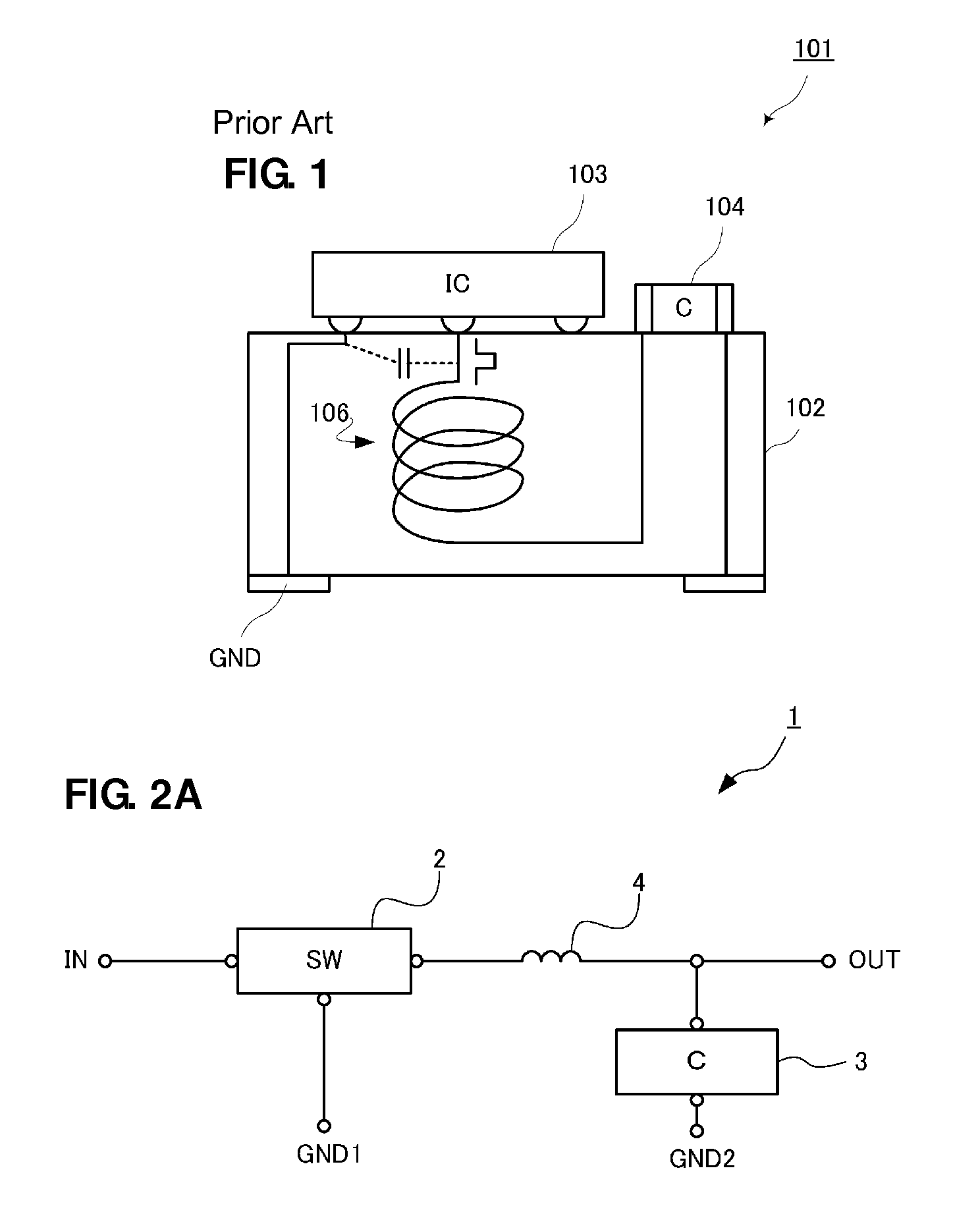
[0029]FIG. 2A is a circuit diagram of a DC-DC converter module 1 according to a first preferred embodiment of the present invention.

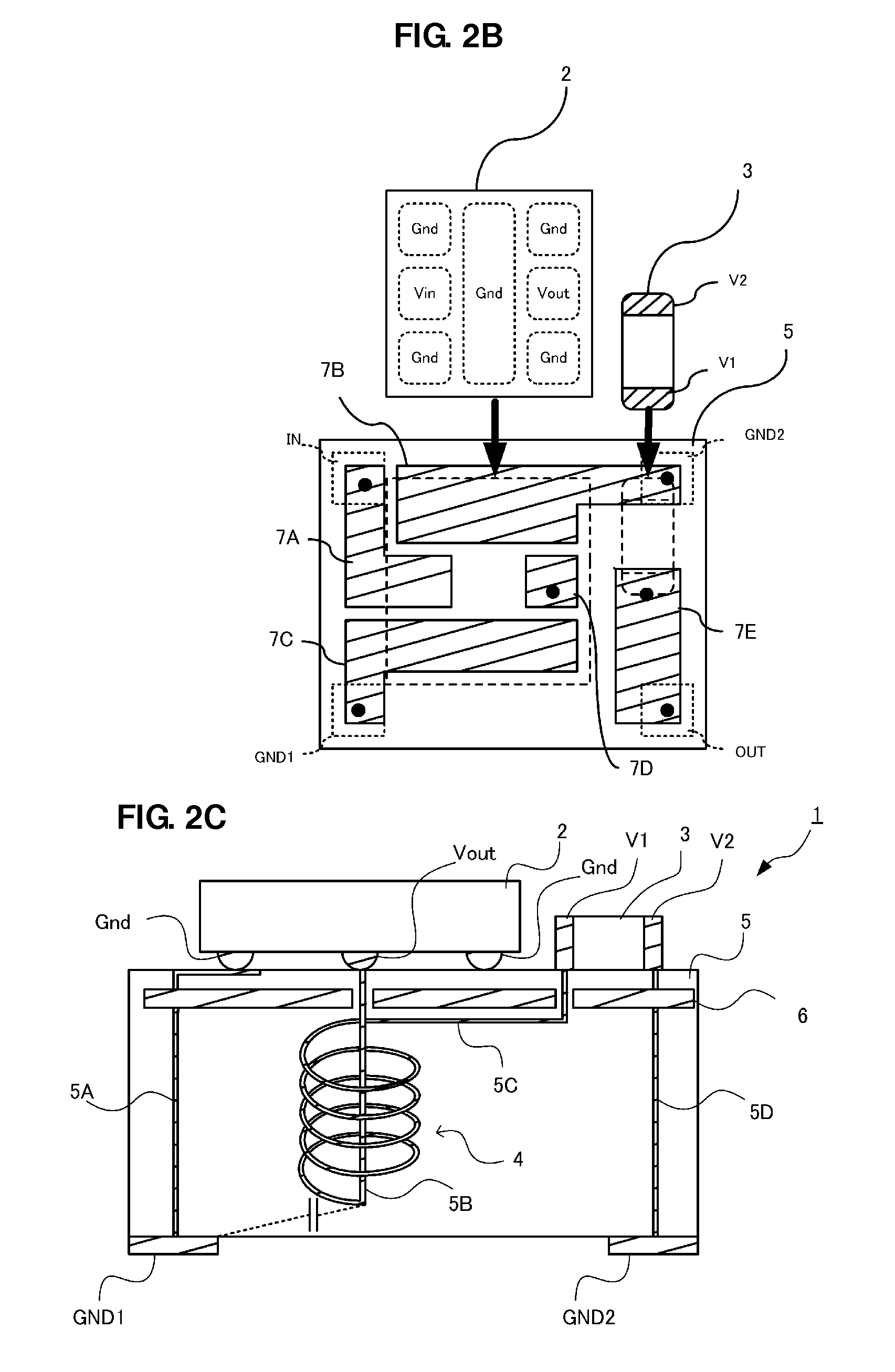
[0030]The DC-DC converter module 1 includes a switching IC 2, a capacitor 3, and a coil 4, as circuit components, and includes an input terminal IN, an output terminal OUT, and ground terminals GND1 and GND2, as external terminals.

[0031]The input terminal IN is connected to an input electrode of the switching IC 2, the ground terminal GND1 is connected to a ground electrode of the switching IC 2, and the output terminal OUT is connected to an output terminal of the switching IC 2. A voltage input to the input terminal is switched by the switching IC 2 and output from the output electrode.

[0032]The coil 4 is connected in series between the output electrode of the switching IC 2 and the output terminal OUT. One end of the capacitor 3 is connected to a node between the coil 4 and the output terminal OUT and the other end is connected to the ground terminal...

second preferred embodiment

[0044]FIG. 3A is a schematic cross-sectional view of a DC-DC converter module 11 according to a second preferred embodiment of the present invention. Unlike the first preferred embodiment, in the DC-DC converter module 11, a shield layer 16 is provided on the bottom surface side, i.e., the second surface side, of the layers where the coil 4 is located in a multi-layer substrate 15.

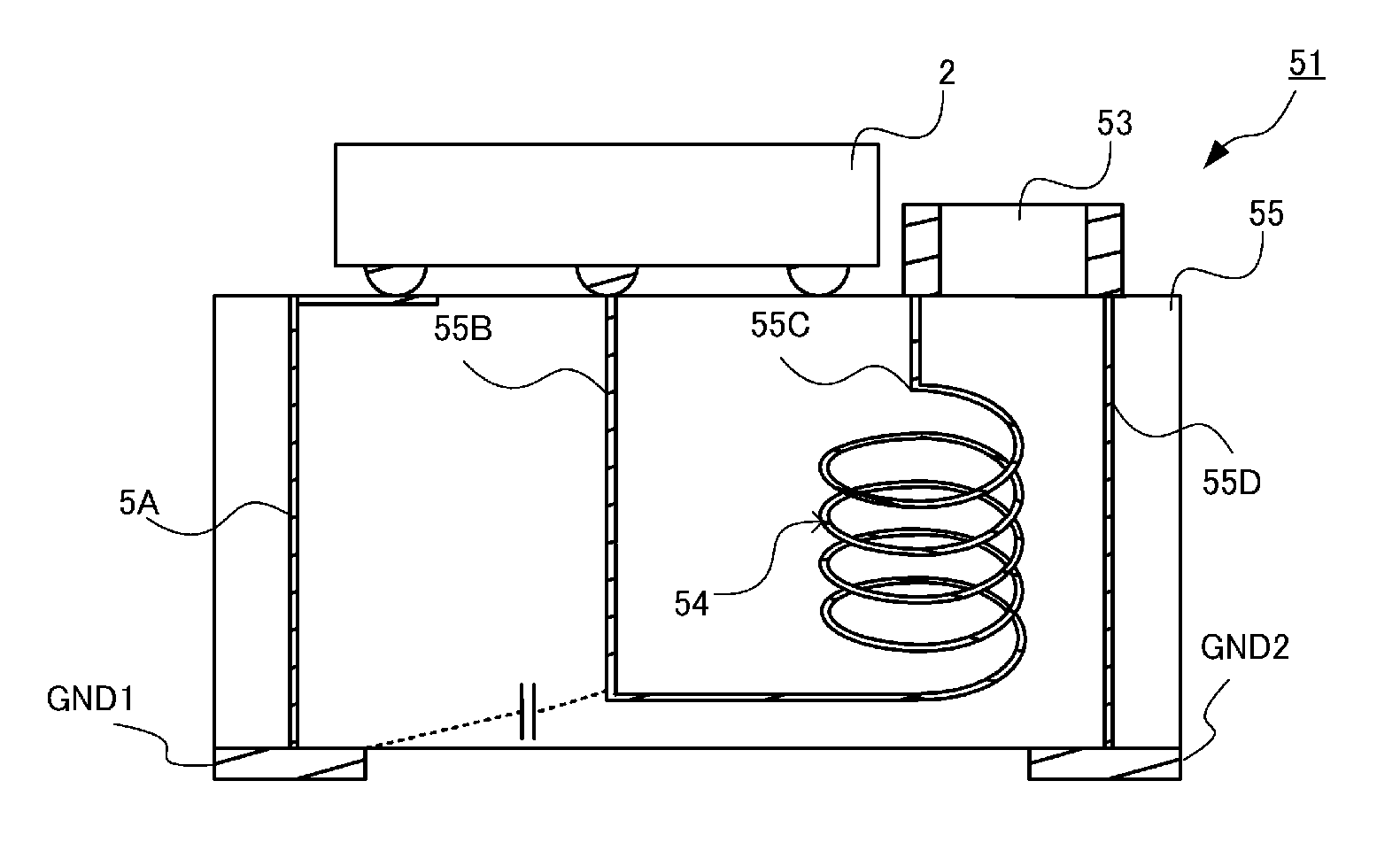
[0045]FIG. 3B is a diagram for explaining the noise characteristics improvement effect obtained by the DC-DC converter module 11 on the basis of a comparative test. In the comparative test, the relationship between the load current and the ripple voltage was measured for the present preferred embodiment and was compared with the relationship between the load current and the ripple voltage for the comparative configuration illustrated in FIG. 2C above. In the figure, the horizontal axis represents load current and the vertical axis represents ripple voltage. The solid line corresponds to the present preferr...

third preferred embodiment

[0047]FIG. 4 is schematic cross-sectional view of a DC-DC converter module 21 according to a third preferred embodiment of the present invention. Unlike the first preferred embodiment, a multi-layer substrate 25 is arranged such that a shield layer is omitted in the DC-DC converter module 21 of the present preferred embodiment. Even with this configuration, the effect of the wiring impedance of the wiring line 5A which is a common impedance for noise is suppressed and significantly reduced, and noise transmitted over the wiring line 5A is suppressed and significantly reduced, such the noise characteristics of the DC-DC converter module 21 are significantly improved.


PUM

PropertyMeasurementUnit
input voltageaaaaaaaaaa
switched voltageaaaaaaaaaa
magneticaaaaaaaaaa

Abstract

A DC-DC converter module includes a multi-layer substrate, a switching IC, and a coil. The multi-layer substrate includes component mounting electrodes provided on the top surface and an input terminal, an output terminal, and ground terminals provided on the bottom surface. The switching IC switches an input voltage and includes an input electrode, an output electrode, and a ground electrode, and is mounted on the top surface of the substrate by connecting the electrodes to the component mounting electrodes. The coil is arranged within the multi-layer substrate in a spiral shape with an axis extending in the substrate stacking direction. The bottom surface side end of the coil is connected to the input / output electrode of the switching IC.

Description

BACKGROUND OF THE INVENTION[0001]1. Field of the Invention[0002]The present invention relates to DC-DC converter modules including a DC-DC converter provided on a multi-layer substrate, and multi-layer substrates.[0003]2. Description of the Related Art[0004]Power supply circuits for portable devices use a linear regulator type or switching regulator type ultra compact regulator module. A linear regulator type module has a low voltage conversion efficiency since all the voltage variation components are converted into heat, and a switching regulator type module has inferior noise characteristics due to switching noise or the like. Hence, it is desired that a DC-DC converter that has a high voltage conversion efficiency and good noise characteristics be reduced in size so as to be usable in a power supply circuit of a portable device or the like.[0005]To reduce the size of a DC-DC converter, the DC-DC converter may be formed in a multi-layer substrate including a magnetic body therein ...

Claims


Application Information

Patent Timeline
Patent Type & Authority Patents(United States)
IPC IPC(8): B23K11/24H05K1/02H02M3/158H02M1/44H05K1/16H02M3/04H01F37/00
CPCH05K1/0233H02M1/44H02M3/04H02M3/158H05K1/165H01F37/005H01L2224/16225H01L2224/16235H01L2924/15313H01L2924/19105Y10T307/74H05K1/0231H05K1/0298H05K1/162H05K2201/086H05K2201/10015
Inventor HIEI, TOMOYOSHI
Owner MURATA MFG CO LTD
Why Eureka
Try Eureka