Sensor system and method for the panoramic standoff detection of chemical contaminants on terrestrial surfaces

Active Publication Date: 2016-04-26
UNITED STATES OF AMERICA THE AS REPRESENTED BY THE SEC OF THE ARMY
View PDF15 Cites 4 Cited by
  • Summary
  • Abstract
  • Description
  • Claims
  • Application Information

AI Technical Summary

Benefits of technology

The patent text describes a new type of sensor that can detect and image chemical contaminants. It uses infrared light to measure the unique signature of the contaminants, which are then processed to create a detailed image. The sensor is designed to be highly sensitive and can detect even small amounts of chemical contaminants. It is particularly useful for detecting and imaging liquid chemical warfare agents and other materials that can be life-threatening. The sensor is easy to use and can be directed onto specific areas of concern. The technical effects of this sensor include improved chemical imaging capability and improved standoff detection of chemical contaminants.

Problems solved by technology

While chemical kits are generally useful, they are designed to detect a limited range of conventional chemical agents that are toxic in the range of 10−3 g / person, provide no standoff protection, and may be prone to false negative and positive detections.
IMS systems, however, require direct exposure to the chemical agent and the instruments typically have insufficient resolving power to identify CBW agents before they have reached casualty producing levels.
Practical PIR detection systems have difficulty detecting low levels of CBW surface target contaminants because the surfaces are typically at thermal equilibrium and provide insufficient contrast to identify target contaminants.
Additionally, background radiation and interference encountered in the field can also make detection difficult.

Method used


Image

  • Sensor system and method for the panoramic standoff detection of chemical contaminants on terrestrial surfaces
  • Sensor system and method for the panoramic standoff detection of chemical contaminants on terrestrial surfaces
  • Sensor system and method for the panoramic standoff detection of chemical contaminants on terrestrial surfaces

Examples


Embodiment Construction

[0029]The embodiments herein and the various features and advantageous details thereof are explained more fully with reference to the non-limiting embodiments that are illustrated in the accompanying drawings and detailed in the following description. Descriptions of well-known components and processing techniques are omitted so as to not unnecessarily obscure the embodiments herein. The examples used herein are intended merely to facilitate an understanding of ways in which the embodiments herein may be practiced and to further enable those of skill in the art to practice the embodiments herein. Accordingly, the examples should not be construed as limiting the scope of the embodiments herein.

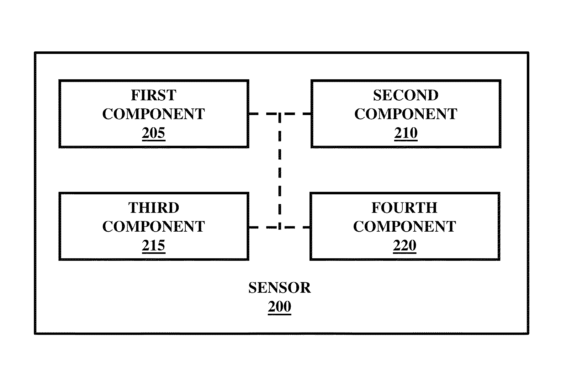
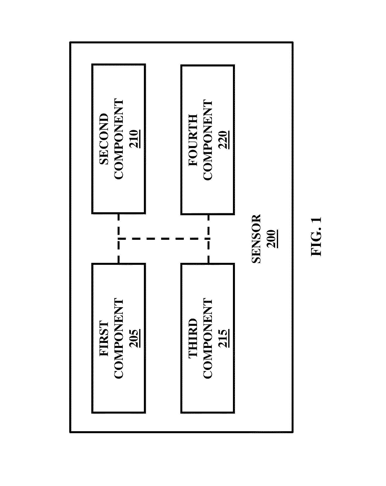
[0030]The embodiments herein provide a pseudo-active chemical imaging sensor including irradiative transient heating, temperature nonequilibrium thermal luminescence spectroscopy, differential hyperspectral imaging, and artificial neural network technologies integrated together. Referring now t...


PUM


Abstract

A pseudo-active chemical imaging sensor including irradiative transient heating, temperature nonequilibrium thermal luminescence spectroscopy, differential hyperspectral imaging, and artificial neural network technologies integrated together. The sensor may be applied to the terrestrial chemical contamination problem, where the interstitial contaminant compounds of detection interest (analytes) comprise liquid chemical warfare agents, their various derivative condensed phase compounds, and other material of a life-threatening nature. The sensor measures and processes a dynamic pattern of absorptive-emissive middle infrared molecular signature spectra of subject analytes to perform its chemical imaging and standoff detection functions successfully.

Description

GOVERNMENT INTEREST[0001]The invention described herein may be manufactured, used, and / or licensed by or for the United States Government.BACKGROUND[0002]1. Technical Field[0003]The embodiments herein generally relate to chemical detection technology, and more particularly to chemical imaging of suspect chemically contaminated surfaces and standoff detection of subject chemical contaminants.[0004]2. Description of the Related Art[0005]A variety of systems and methods have been developed and used to detect and identify hazardous chemical and biological threat agents in the field. Chemical test kits that employ chemically reactive vapor-samplers and detection papers have long been used to detect chemical nerve agents, blood agents, and blister agents. While chemical kits are generally useful, they are designed to detect a limited range of conventional chemical agents that are toxic in the range of 10−3 g / person, provide no standoff protection, and may be prone to false negative and po...

Claims


Application Information

Patent Timeline
IPC IPC(8): G01N21/23G01N21/27G01N21/71
CPCG01N21/27G01N21/71G01B9/02G01J3/447G01J3/45G05B13/027G01N21/31G01N21/94G01N2201/1296G01J3/0291G01J3/0205G01J3/453G01J3/4537G01J3/0208G01J3/0224G01J3/0286
Inventor CARRIERI, ARTHUR H.BUICAN, TUDOR N.ROESE, ERIK S.SUTTER, JAMESSAMUELS, ALAN C.
Owner UNITED STATES OF AMERICA THE AS REPRESENTED BY THE SEC OF THE ARMY
Why Eureka
Try Eureka