Log-periodic dipole array antenna and smart skin having the same

a dipole array and dipole array technology, applied in the structural form of non-resonant long antennas, resonant antennas, radiating elements, etc., can solve the problems of increasing the weight and size of a system, increasing the cost, etc., and achieve the effect of reducing the weight and size of the system and improving the signal quality

Active Publication Date: 2016-06-14
AGENCY FOR DEFENSE DEV
View PDF8 Cites 4 Cited by
  • Summary
  • Abstract
  • Description
  • Claims
  • Application Information

AI Technical Summary

Benefits of technology

[0009]Another aspect of the detailed description is to provide a log-periodic dipole array (LPDA) antenna having a more improved structure and a better antenna performance.
[0014]In accordance with one exemplary embodiment, the first frequency band may be higher than the second frequency band, and the band stopper may be located adjacent to an upper side of the radiating element to reduce antenna gain with respect to a signal adjacent to the first frequency band.
[0015]In accordance with one exemplary embodiment, the first frequency band may be higher than the second frequency band, and the band stopper may be located adjacent to a lower side of the radiating element so as to reduce antenna gain with respect to the second frequency band.
[0017]A log-periodic dipole array antenna in accordance with at least one exemplary embodiment may improve qualities of signals associated with characteristics of reflection loss and gain in a desired frequency band, and allow for reduction of weight and size of a system by virtue of non-use of an additional filter circuit.

Problems solved by technology

This causes an additional cost increase and an increase in weight and size of a system.

Method used


Image

  • Log-periodic dipole array antenna and smart skin having the same
  • Log-periodic dipole array antenna and smart skin having the same
  • Log-periodic dipole array antenna and smart skin having the same

Examples


Embodiment Construction

[0028]Description will now be given in detail of a log-periodic dipole array antenna according to the exemplary embodiments, with reference to the accompanying drawings. Hereinafter, suffixes “module” and “unit or portion” for components used herein in description are merely provided only for facilitation of preparing this specification, and thus they are not granted a specific meaning or function. Hence, it should be noticed that “module” and “unit or portion” can be used together. For the sake of brief description with reference to the drawings, the same or equivalent components will be provided with the same reference numbers, and description thereof will not be repeated. The expression in the singular form in this specification will cover the expression in the plural form unless otherwise indicated obviously from the context.

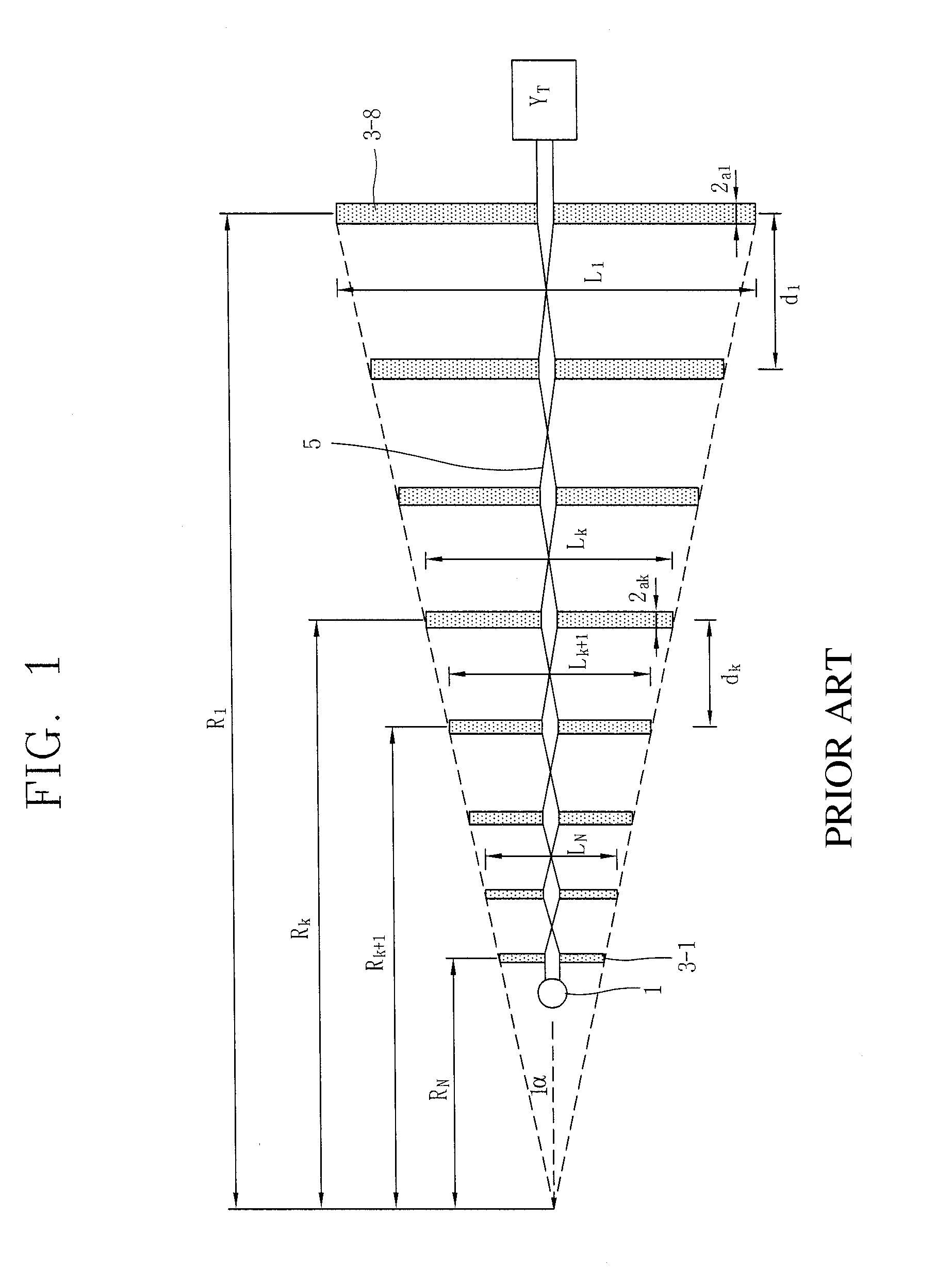
[0029]FIG. 1 illustrates the structure and design parameters a conventional log-periodic dipole array antenna.

[0030]A conventional log-periodic dipole array...


PUM


Abstract

A log-periodic dipole array antenna according to one exemplary embodiment of the present disclosure includes a dielectric substrate, a radiating element having a plurality of lines extending from a center to an outer side and symmetrically arranged on the dielectric substrate based on the center, so as to resonate in a first frequency band and a second frequency band, the plurality of lines being connected at the center or the outer side of the radiating element in an alternating manner, the lines becoming longer going from up to down of the radiating element fed according to a predetermined log-periodic ratio, and a band stopper formed on one point for connecting the lines to each other.

Description

CROSS-REFERENCE TO RELATED APPLICATION[0001]Pursuant to 35 U.S.C. §119(a), this application claims the benefit of earlier filing date and right of priority to Korean Application No. 10-2013-0016466, filed on Feb. 15, 2013, the contents of which is incorporated by reference herein in its entirety.BACKGROUND OF THE DISCLOSURE[0002]1. Field of the Disclosure[0003]This specification relates to a log-periodic dipole array antenna for transmission and reception of wireless signals.[0004]2. Background of the Disclosure[0005]In general, an antenna switches an electrical signal which is represented with voltage / current and an electromagnetic wave represented with an electric field / magnetic field to each other. Types of antennas include a dipole antenna, a monopole antenna, a patch antenna, a horn antenna, a parabolic antenna, a helical antenna, a slot antenna, a log-periodic dipole array (LPDA) antenna and the like.[0006]Here, the LPDA antenna is a type that periodically repeats the impedanc...

Claims


Application Information

Patent Timeline
Patent Type & Authority Patents(United States)
IPC IPC(8): H01Q11/10H01Q1/42H01Q1/28H01Q15/10H01Q5/307H01Q5/00
CPCH01Q11/105H01Q1/28H01Q1/286H01Q1/42H01Q5/307H01Q15/10H01Q1/24H01Q1/38H01Q9/44
Inventor KIM, MIN SUNGPARK, CHAN YIKYU, BYUNG GILJANG, HO JOON
Owner AGENCY FOR DEFENSE DEV
Why Eureka
Try Eureka