Driver assembly for solid state lighting

a technology for solid-state lighting and driver assembly, which is applied in the direction of lighting apparatus, electric lighting sources, and light sources. it can solve the problems of failure of one or more drivers, and affecting the operation of the entire system, so as to achieve effective heat dissipation, compact footprint, and high functional effect of operation

Inactive Publication Date: 2016-06-28
STEPPS DALE +1
View PDF155 Cites 1 Cited by
  • Summary
  • Abstract
  • Description
  • Claims
  • Application Information

AI Technical Summary

Benefits of technology

[0015]It is an object of the present invention to provide a substantially compact and highly efficient driver assembly for solid-state lighting which can achieve a substantially compact footprint and thereby be functional in a variety of pre-existing environments wherein traditional incandescent or fluorescent lighting is being replaced, without requiring substantial modification or alteration of the existing construction or infrastructure.
[0016]It is a further object of the present invention to provide a driver assembly for solid-state lighting which can effectively dissipate heat in a substantially compact configuration so as to be able to be properly potted in order to define an explosion proof, weather proof, and / or fluid resistant lighting system.
[0017]It is still another object of the present invention to provide a substantially compact and highly efficient solid-state driver assembly which can maintain a substantially small and highly functional operative footprint without being susceptible to magnetic interference and / or cross coupling.
[0018]Yet another object of the present invention is to provide a solid-state driver assembly which can be highly adaptable to a variety of operative power settings without the need to interchange and / or directly reconfigure operative components.
[0019]It is an object of the present invention to provide a substantially compact and completely insulated solid-state driver assembly which can be pre-manufactured and effectively customized even after initial manufacture and installation.

Problems solved by technology

A significant problem associated with the use of solid-state lighting, however, relates to complications that arise in connection with the driver that is utilized to power the LED light.
As part of this power management and control process, however, the drivers are particularly susceptible to overheating given the nature of the components and the manner in which they are being utilized.
Further, overheating does not merely cause a problem within the context of generating unwanted heat into an environment, but is especially problematic in sold state lighting as it can lead to failures in one or more components of the driver, and thus a malfunction or shut down of the entire system.
Unfortunately, however, inefficiencies in the configuration and design of the operative circuitry of traditional drivers and heat sinks still result in greater than optimal levels of failure, and require that the drivers and heat sinks be substantially large so as to effectively manage the heat by providing a large surface area from which the heat can be dissipated.
As a result, LED based solid state lighting has seen limited applicability where a substantial amount of light is needed.
Further, when attempts have been made to provide greater illumination using LEDs, illumination systems with large driver bars and heat sinks must typically be employed so as to provide a large surface area for heat dissipation, thus requiring a large mounting surface and a larger footprint than may be optimal.
A further significant limitation associated with the field of solid-state lighting relates to the inapplicability of cost effective solid-state lighting in a variety of environments and in particular environments wherein all lighting and fixtures must be explosion proof.
Because of the nature of traditional solid-state driver assemblies, there is always some risk of uncontainable sparks or explosions at the driver, and the large size of traditional driver assemblies makes it impractical to properly address this risk.
Another factor that often leads to the requirement that a solid-state driver have a substantially large size, thereby making it impractical for a variety of applications, relates to the risk of magnetic interference and more particularly cross coupling between components such as the input and output inductors.
Of course, because of the already present requirement for a large surface area in order to effectively dissipate heat, the large spacing necessary is often available to allow for this effective separation, and no alternate solution has been contemplated.
As a result, this provides yet another reason to require larger sized driver assemblies that in turn limit the applicability of the solid-state lighting to environments that can accommodate a larger fixture and driver assembly, and that can accommodate the larger material and installation costs associated with larger footprint driver assemblies.
Still another drawback associated with traditional solid-state driver assemblies relates to the ever increasing need for power output customization.
This need for customization, however, further limits the applicability of traditional driver assemblies and increases the costs associated with their use.
For example, manufacturers of the driver assemblies are not in a position to manufacture large volumes of different configuration driver assemblies to maintain an effective stock.
Further, this limitation not only increases the costs associated with the manufacture of the drivers and the maintaining of uncompleted inventory, but also limits the effective applicability of the driver assemblies as the drivers cannot be pre-prepared for certain environments, such as an environment that requires an explosion proof driver assembly or a weather resistant driver assembly.

Method used


Image

  • Driver assembly for solid state lighting
  • Driver assembly for solid state lighting
  • Driver assembly for solid state lighting

Examples


Embodiment Construction

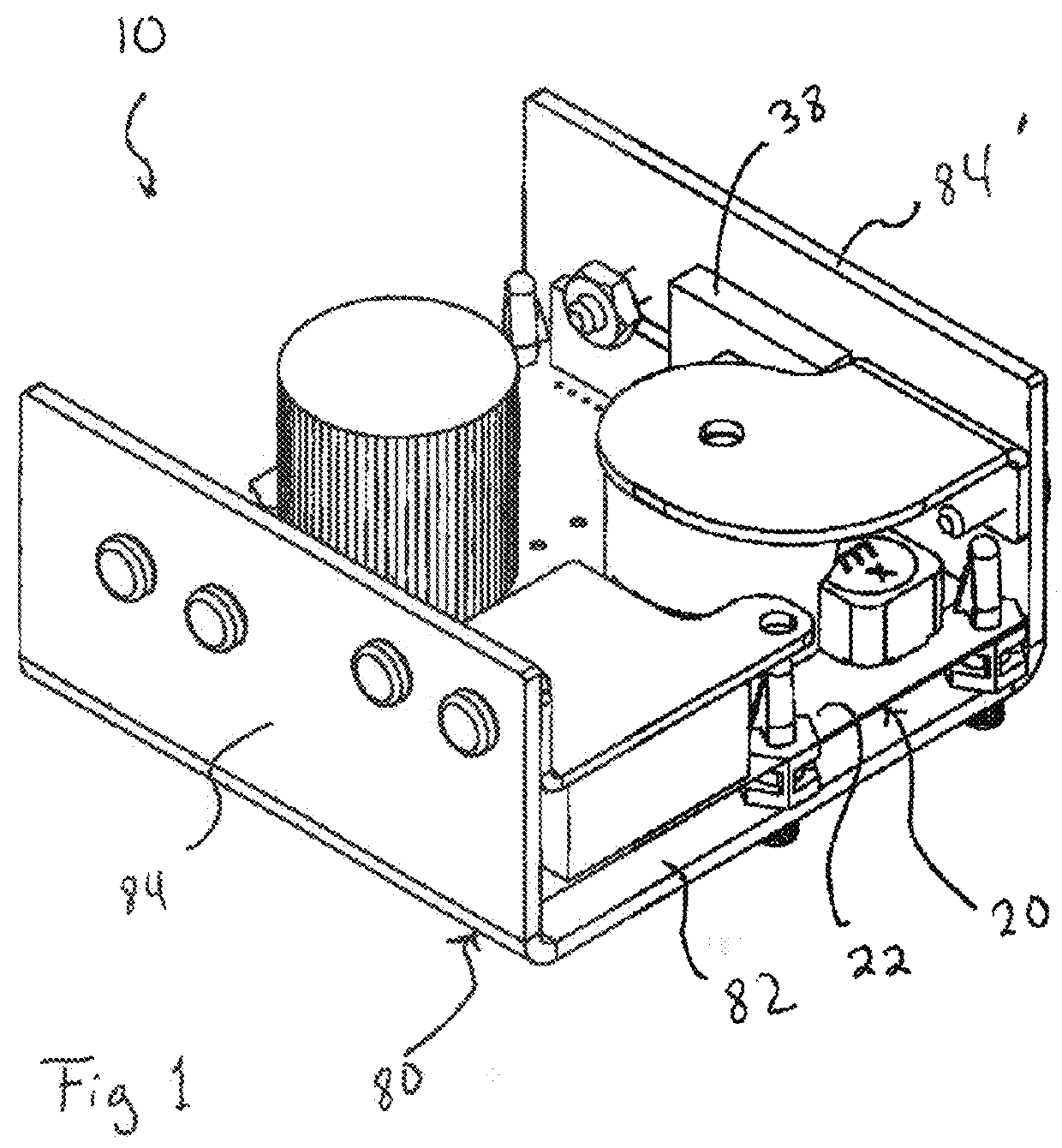
[0028]The present invention is directed towards a driver assembly for solid-state lighting, generally indicated as 10. The driver assembly 10 is specifically configured to power at least one LED, but often will be utilized to power an array of LEDs in order to provide illumination for a particular desired application. In this regard, the driver assembly 10 of the present invention can be utilized for a variety of different lighting applications including indoor applications, outdoor applications, use within hazardous environments, and use in environments wherein the lighting assembly will be susceptible to adverse weather and / or liquids.

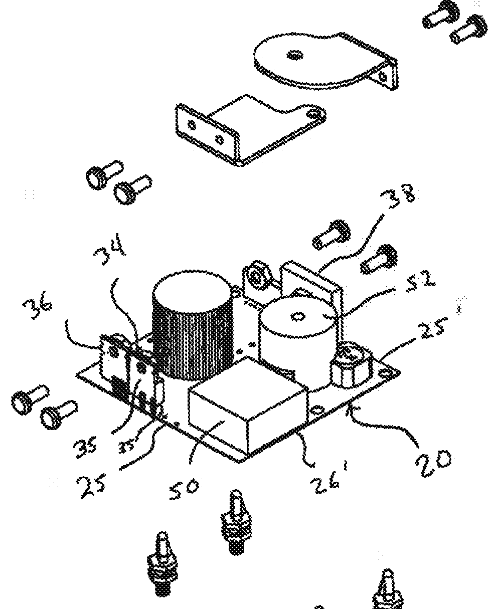
[0029]In a preferred embodiment of the present invention, the driver assembly 10 includes a base element, generally 20. The base element 20 is preferably constructed of a generally rigid material onto which a plurality of operative components can be secured. As such, it is preferred that the base element 20 comprise a printed circuit board (PCB). Alt...


PUM


Abstract

A driver assembly for solid state lighting that includes at least one LED which includes a base element having an upper surface, a lower surface, an outer peripheral edge extending about a periphery thereof and a perimeter region defined adjacent to the outer peripheral edge. A plurality of operative components are secured to the base element and are collectively operative at least 40 watts in order control current flow to the LED. The plurality of operative components include primary heat generating components and heat sensitive components, with the primary heat generating components disposed on the perimeter region of the base element and the heat sensitive component disposed in spaced relation from the peripheral region at which the primary heat generating components are disposed. The primary heat generating components are disposed in a vertical orientation wherein a vertical surface that extends away from the base element has a greater surface area than a horizontal surface that confronts the base element. Further provided is a heat sink which has a pair of vertical elements formed of a thermally conductive material, the vertical elements extending upward along part of the outer peripheral edge of the base element in confronting, heat receiving relation to the vertical surfaces of the primary heat generating components.

Description

BACKGROUND OF THE INVENTION[0001]1. Field of the Invention[0002]The present invention relates to a driver assembly for solid state lighting wherein the driver assembly is substantially compact and efficient so as to achieve a variety of uses, can achieve a varied range of power outputs without overheating, and is sufficiently contained so as to be usable in a setting wherein an explosion proof fixture is necessary.[0003]2. Description of the Related Art[0004]Solid state lighting, and in particular the powering and use of LEDs for lighting is becoming increasingly popular as a highly efficient and energy conscious form of illumination that can be used in a number of different applications to replace traditional incandescent or fluorescent lighting. A significant problem associated with the use of solid-state lighting, however, relates to complications that arise in connection with the driver that is utilized to power the LED light. Specifically, because LED lights operate at lower vo...

Claims


Application Information

Patent Timeline
Patent Type & Authority Patents(United States)
IPC IPC(8): H01K1/62H05B33/08H05B44/00
CPCH05B33/0803H05B45/30
Inventor STEPPS, DALESUAREZ, JOSE
Owner STEPPS DALE
Why Eureka
Try Eureka