
Separator and method for separation

a separation device and separation method technology, applied in the field of separation devices, separation methods, and liquid separation agents, can solve the problems of increasing the cost, occupying space, weight and instrumentation, and affecting the operation of downstream facilities

Active Publication Date: 2016-07-12
GASOLINEIAM NASIONAL BERHAD +1
View PDF7 Cites 2 Cited by
  • Summary
  • Abstract
  • Description
  • Claims
  • Application Information

AI Technical Summary

Benefits of technology

[0019]With the separator having a gas scrubber in close proximity, the ability to more efficiently recycle liquid, the invention is able to reduce space and save on capital infrastructure costs, providing advantage over the prior art.
[0020]In one embodiment, by actually mounting the scrubber to the separation chamber, further space savings may be achieved.
[0027]In one embodiment, the stilling well may include a sand removal assembly within the sand trap, said sand trap assembly including at least cyclonic device for agitating sand into suspension, and a valve controlled outlet for discharging liquid having the sand in suspension. In effect, having the sand in suspension allows the sand to be moved by flowing the liquid out of the sand trap, and thus using the liquid as a sand removal medium. Further, the sand removal assembly may also have an intermediate sand trap having a further valve controlled outlet arranged such that the liquid is discharged to the intermediate sand trap, prior to final discharge. Further still, the intermediate sand trap includes a further cyclonic device for agitating liquid in the intermediate sand trap prior to final discharge.

Problems solved by technology

However, field experience indicates that many of these systems experience significant liquid carry-over which has resulted in problems and damage of downstream facilities like the gas compressions.
This adds to space, weight and instrumentation (due to additional level monitoring and control) which in turn results in increased cost.
The reliability, availability and maintainability of the system are also reduced due to the additional equipment and associated instrumentation.
For facilities where the inlet fluid is from a pipeline, slug flow in the pipeline results in significant sloshing, liquid entrainment and a drastic change in liquid level at the inlet separator.
This turbulence at the inlet separator may result in a significant amount of liquid collecting around the gas outlet device at the separator.
This, in turn, will result in both high liquid entrainment into the gas stream out of the separator and also potential blockage of the separator outlet device particularly if the liquid is waxy.
The blockages occur as a result of cold spots at the gas outlet device; with the effect made worse by the normally small flow path associated with the internals.
“Sloshing” of the liquid phase may also lead to liquid coming into contact with the gas outlet device.
If the liquid entrained in the gas stream is waxy, there is no means of removing the wax that builds up at the device unless the separator is taken offline, and the outlet device disassembled.
This increases the size of the separator.
In particular, waxy crude that forms gel or crystalline structure at lower temperatures normally leads to a number of operational problems especially the ability of the fluid to flow and clogging of the instruments and internals that is integral to the performance of the equipment.
However it is unavoidable that some cold spots will develop within the system.
Low specific heat means that the gas gains or loses temperature faster.
The problem of wax is compounded within all such separation, as the gas phase internals are normally built into the inlet separator and consists of small flow paths and parts, and further, with the gas phase in direct contact with the oil phase.
Also, it has been found that slugging, or surges, lead to more liquids carryover in the gas phase.
For specific FPSO applications, the motion of the vessel may make the above problem worse.
Furthermore, there is no means for early detection of the waxing problems, and no means to fix the problem online if the wax begins to form.
And when wax begins to form, the problem is self propagating.
This however increases the space and weight requirements and in addition increases the control, operational & maintenance complexity of the system.
A further problem involves slugging which is a challenging problem for many crude oil production receiving facilities particularly those receiving production from multi-phase subsea pipelines as they are susceptible to slugs.
Slugs generated in the pipelines and risers not only require processing facilities to be increased in size to accommodate the slugs, but also results in production upsets associated with the high speed at which the slugs arrive and the transient pressure fluctuations due to the surge of gas following the arrival of the slug.
Under these scenarios the production facilities like inlet heat exchangers, production separators and downstream gas compressors generally will not be able to cope with this transient slugging phenomenon resulting in production upsets and possibly shutdown.
After the slug arrives at the outlet of the pipeline or production platform, the compressed gas creates a large gas surge, which again may result in major upsets in topside facilities, like the downstream gas compression trains.
Without any effective separation upstream, the slug flow conditions at the heater results in large heating duties of the exchanger as both the gas stream and the liquid streams are heated.
The excessive heating duties results in poor performance of the heat exchanger, thus waxy crude and emulsions are still of existence in the outlet stream.
Furthermore, the system experiences large pressure drop as the heating duty is high.
On the other hand, the existence of waxy crude and emulsions will cause blockages at the inlet and outlets of the separator.
Although the separation of oil, gas and water can be performed, the exiting gas stream will comprise significant liquid entrainment that will cause damage to the condensing system, resulting in system shutdown.
Hence, the reliability of the separator system is very low.
In addition, these turbulences and the ineffective heating of the inlet fluids leading to the presence of water emulsion, inherent with multiphase fluids under slugging conditions will also result improper oil water separation in the separator.
This will require the downstream system to be upsized due to excessive water carry-over in oil stream and excessive oil carry-over in the water stream.
Furthermore, the presence of sand in the production fluid often results in sand build-up in the downstream separator which in turn possibly requires frequent shutdowns to remove sand from the separator or requires sand removal devices to be installed at the separator which are expensive.

Method used


Image

  • Separator and method for separation
  • Separator and method for separation
  • Separator and method for separation

Examples


Embodiment Construction

[0038]The invention provides a separator developed for the oil and gas industry where a two phase (gas and liquid) or 3 phase (gas, oil and water) separator which, in various embodiments, may have the advantages of providing high liquid droplet removal efficiency, may be compact with minimal space and weight and may require less controls and instrumentations. The system may be suitable for both onshore and offshore applications where space is limited and may be suitable for waxy and fouling fluid services and for facilities where motion effects are high, e.g. FPSOs.

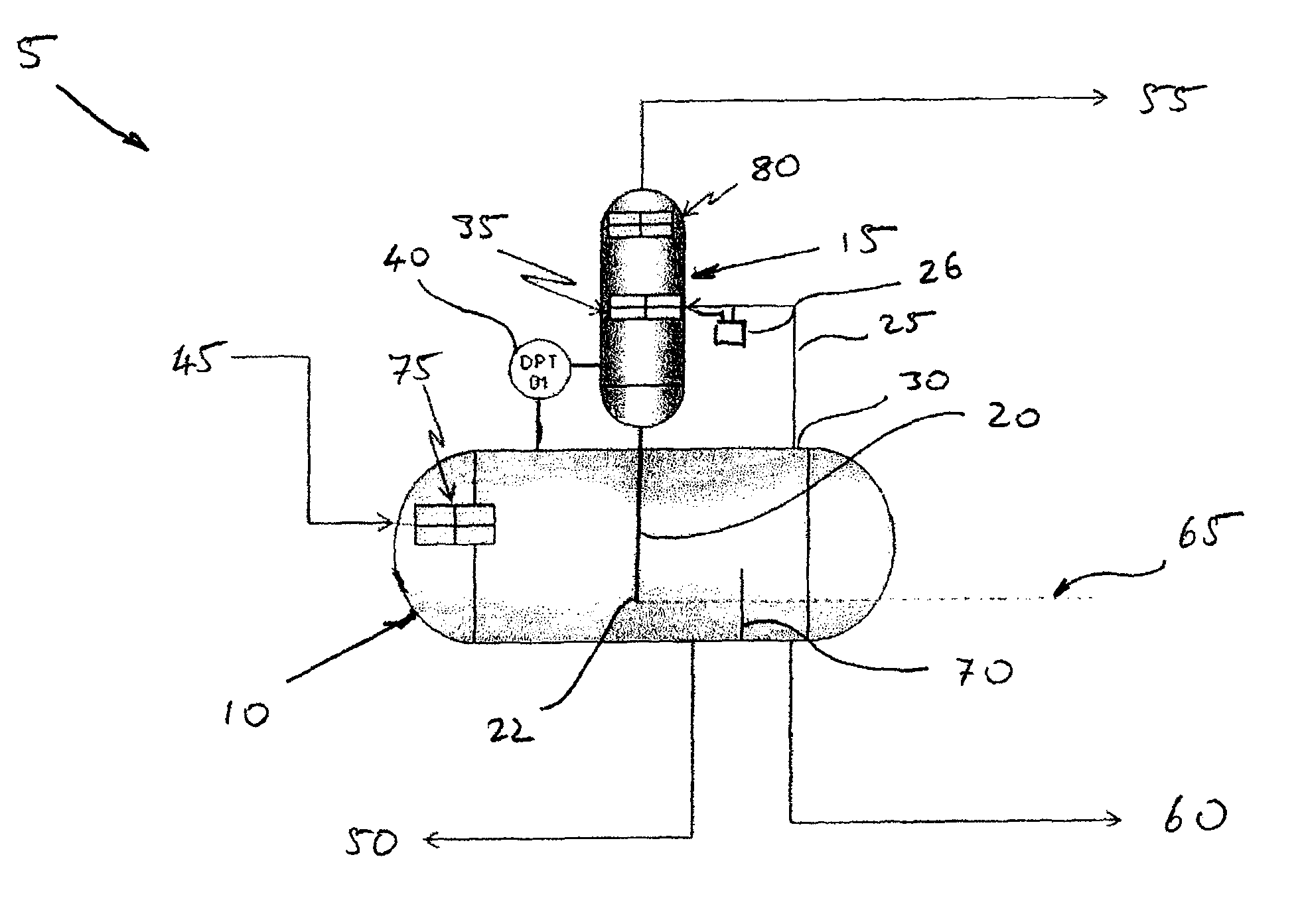
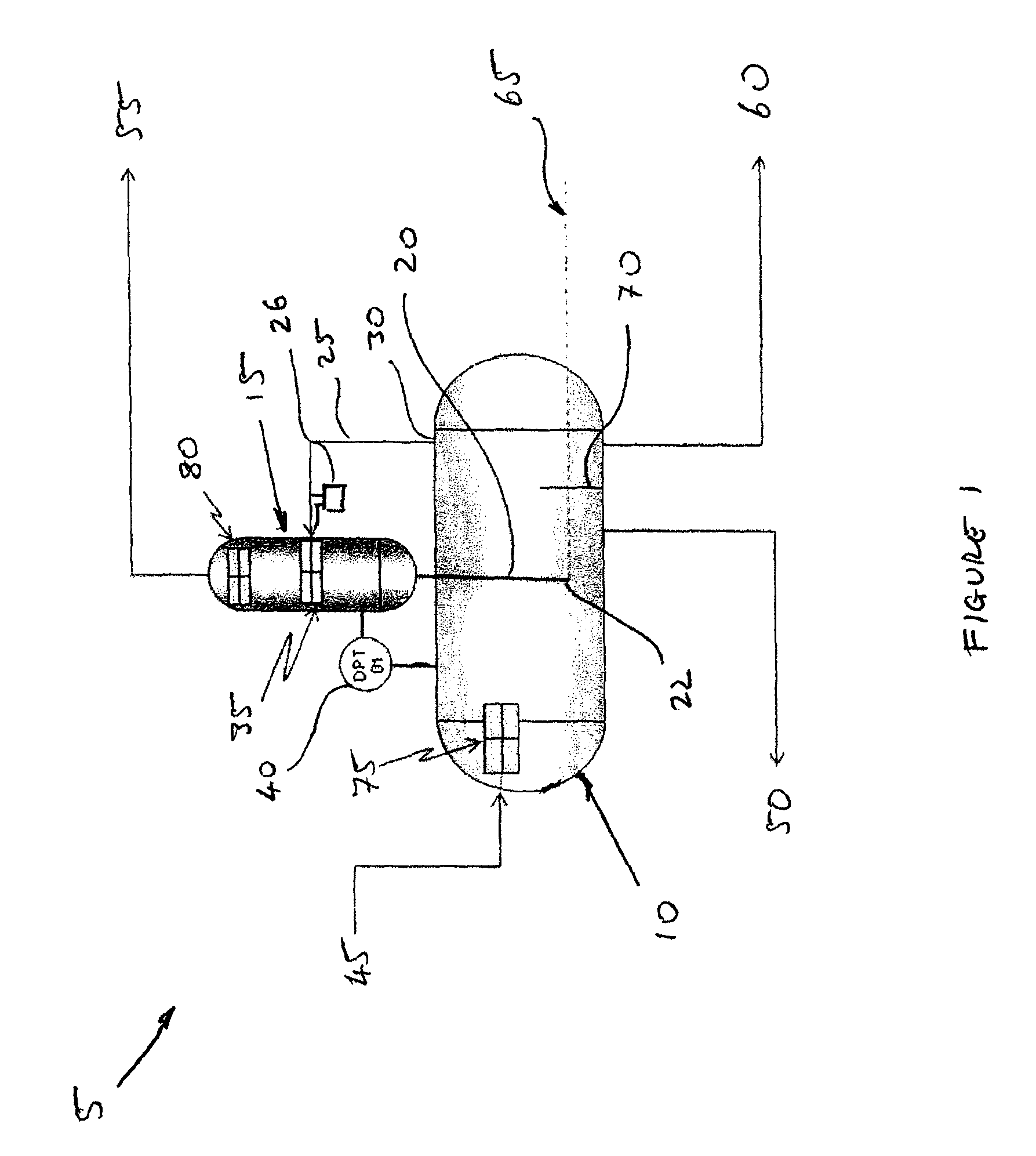
[0039]FIG. 1 gives the schematic of the separator system 5 of this invention to enable bulk gas / liquid separation and efficient gas polishing. The separation system 5 comprises two sections, the bulk gas liquid separation chamber 10 and a gas polishing scrubber section 15 as an integrated unit 5.

[0040]The separator chamber 10 is similar to a three phase gas-liquid separator whereby production fluid 45 comprising a gas and...


PUM

PropertyMeasurementUnit
depthaaaaaaaaaa
lengthaaaaaaaaaa
pressure dropaaaaaaaaaa

Abstract

A separator system (5) comprising; a separation chamber (10) arranged to separate liquid from an inflow production fluid (45); at least one gas scrubber (15) for removing entrained liquid from a separated gas inflow from said separation chamber (10); wherein said at least one gas scrubber (15) is positioned above and proximate to said separation chamber (10), said gas scrubber (15) and separation chamber (10) connectable through a vertically oriented at least one liquid outflow conduit (20) arranged to direct the removed entrained liquid from the gas scrubber (15) to the separation chamber (10) wherein the conduit (20), is arranged such that an outflow end (22) of said conduit (20) extends into the separation chamber 10(10) such that it is lower than a minimum threshold liquid depth (65) in said separation chamber 10(10).

Description

[0001]This application is the U.S. national phase of International Application No. PCT / IB2012 / 000128 filed Jan. 30, 2012, which designated the U.S. and claims priority to PI 2011000489 filed Jan. 31, 2011, the entire contents of each of which are hereby incorporated by reference.FIELD OF INVENTION[0002]The invention relates to a system and method for the separation of gas and liquid, and particularly relates to applications for the oil and gas industry. In particular, the invention relates to a separator, and method of separation, in order to isolate gas, oil and water from a natural inflow prior to the refining process.BACKGROUND[0003]A conventional means of separating gas, oil and water is using a three-phase separator. However, field experience indicates that many of these systems experience significant liquid carry-over which has resulted in problems and damage of downstream facilities like the gas compressions. To mitigate this, an additional polishing scrubber is generally pro...

Claims


Application Information

Patent Timeline
Patent Type & Authority Patents(United States)
IPC IPC(8): B01D53/18B01D17/02B01D45/02B01D45/08B01D53/14B01D21/02
CPCB01D53/1425B01D17/0211B01D17/0214B01D45/02B01D45/08B01D53/18B01D21/02B01D2221/04B01D53/14B01D53/78
Inventor ZAINAL ABIDIN, SHAHRUL AZMAN BJOTHY, ARUL
Owner GASOLINEIAM NASIONAL BERHAD
Learn More