Variable-wavelength interference filter, optical filter device, optical module and electronic apparatus

a variable-wavelength interference filter and filter device technology, applied in the direction of optical radiation measurement, instruments, spectrometry/spectrophotometry/monochromators, etc., can solve the problems of resolution decrease, half-value width of light transmitted through the variable-wavelength interference filter increas

Inactive Publication Date: 2016-07-12
SEIKO EPSON CORP
View PDF16 Cites 2 Cited by
  • Summary
  • Abstract
  • Description
  • Claims
  • Application Information

AI Technical Summary

Benefits of technology

[0115]In this embodiment, the first reflection layer 551 and the second reflection layer 552 have a reflectance characteristic showing a reflectance that increases from the short-wavelength side toward the long-wavelength side. Thus, the half-value width of light extracted by the variable-wavelength interference filter 5 can be made uniform.
[0116]That is, in the configuration in which the reflection layer of an Ag alloy as shown in FIG. 8A is used and the inter-layer gap 01 is narrowed, when light on the long-wavelength side is transmitted through the variable-wavelength interference filter, the second reflection layer 552 has no flexure or gradient and the reflectance of the reflection layer is high. Therefore, high-resolution light with a small half-value width can be extracted. Meanwhile, in such a related-art variable-wavelength interference filter, when light on the short-wavelength side is transmitted, the second reflection layer 552 has flexure or gradient and the reflectance of the reflection layer is lower than on the long-wavelength side. Therefore, low-resolution light with a large half-value width is extracted. Thus, with the related-art variable-wavelength interference filter, the half-value width decreases from the short-wavelength side toward the long-wavelength side and it is difficult to extract light with uniform resolution.
[0117]On the contrary, according to this embodiment, on the short-wavelength side, even if the reflectance of the reflection layers 551, 552 is lower than on the long-wavelength side, the flexure or gradient of the second reflection layer 552 is restrained and therefore light with higher resolution can be extracted, compared with the related-art variable-wavelength interference filter. Meanwhile, on the long-wavelength side, the resolution is lower than in the related-art variable-wavelength interference filter, because of the influence of the flexure or gradient of the second reflection layer 552. Therefore, in this embodiment, whatever wavelength of light is extracted from a preset wavelength range, the half-value width can be made substantially uniform and the light can be extracted with substantially constant resolution.
[0118]Thus, in the spectroscopic measuring device 1, for example, when acquiring a spectrum of measuring target light, the inconvenience that measuring reliability on the short-wavelength side is lower than measuring reliability on the long-wavelength side, or the like, can be avoided and an accurate spectrum can be acquired.
[0119]Also, according to this embodiment, AlAs films are used as the first reflection layer 551 and the second reflection layer 552. Such AlAs film has a reflection characteristic over a broad wavelength range from visible range to near-infrared range. Therefore, the a broad range can be set as a measuring target wavelength range of the variable-wavelength interference filter 5.Second Embodiment
[0120]Next, a second embodiment of the invention will be described.

Problems solved by technology

Therefore, when the inter-layer gap is narrowed in order to extract light on the short-wavelength side, there is a problem that the half-value width of light transmitted through the variable-wavelength interference filter increases (resolution decreases) as the inter-layer gap is narrowed because of the flexure and gradient of the second substrate.

Method used


Image

  • Variable-wavelength interference filter, optical filter device, optical module and electronic apparatus
  • Variable-wavelength interference filter, optical filter device, optical module and electronic apparatus
  • Variable-wavelength interference filter, optical filter device, optical module and electronic apparatus

Examples


first embodiment

[0055]Hereinafter, a first embodiment of the invention will be described with reference to the drawings.

Configuration of Spectroscopic Measuring Device

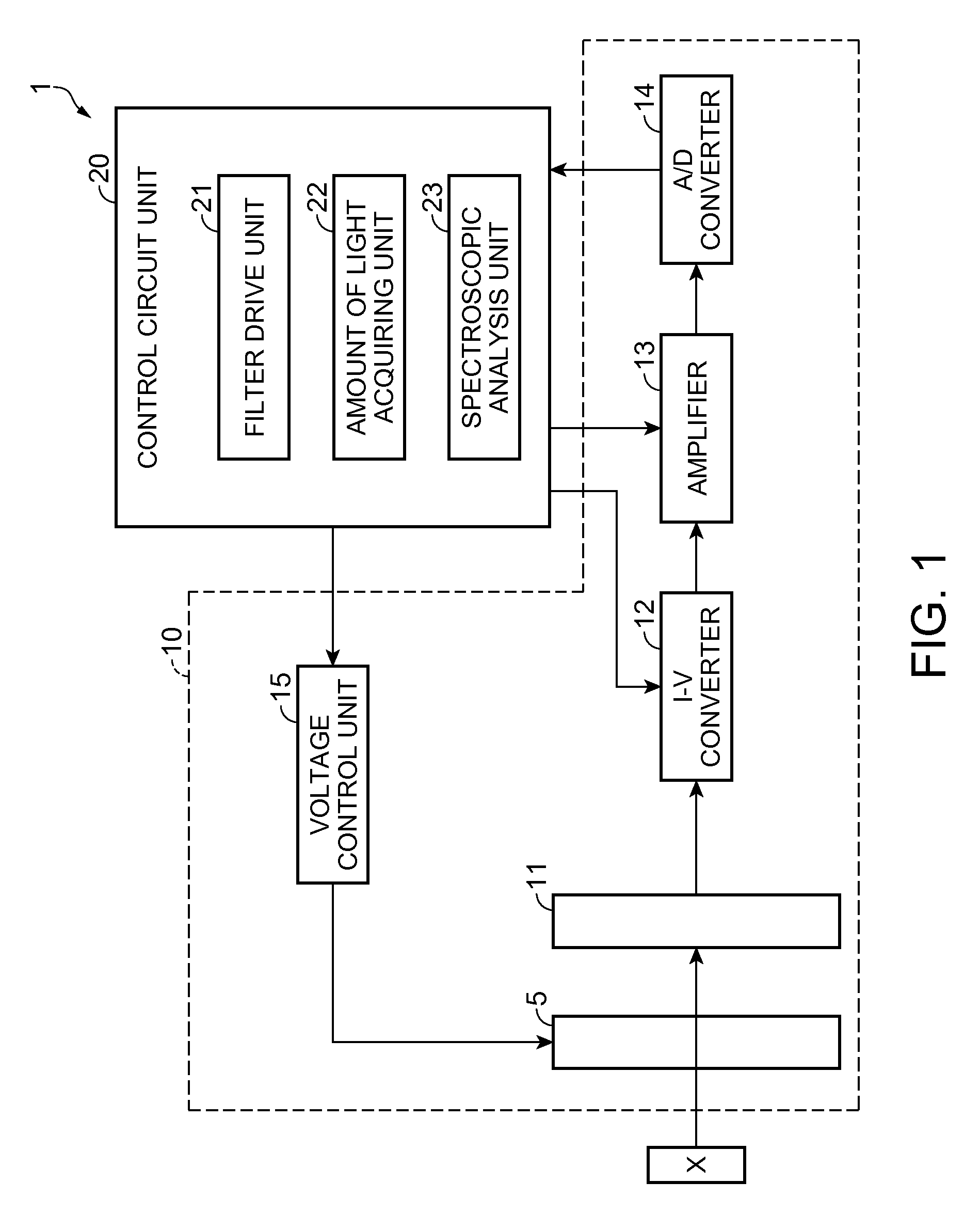
[0056]FIG. 1 is a block diagram showing the schematic configuration of a spectroscopic measuring device according to the embodiment.

[0057]A spectroscopic measuring device 1 is a device which analyzes light intensity of each wavelength of measuring target light reflected by, for example, a measuring target X, and measures the spectrum thereof. While an example in which measuring target light reflected by the measuring target X is measured is illustrated in this embodiment, if a light emitting body, for example, a liquid crystal panel or the like, is used as the measuring target X, light emitted from the light emitting body may be used as measuring target light.

[0058]This spectroscopic measuring device 1 has an optical module 10 and a control circuit unit 20 which processes a signal outputted from the optical module 10.

Configuration of ...

second embodiment

[0120]Next, a second embodiment of the invention will be described.

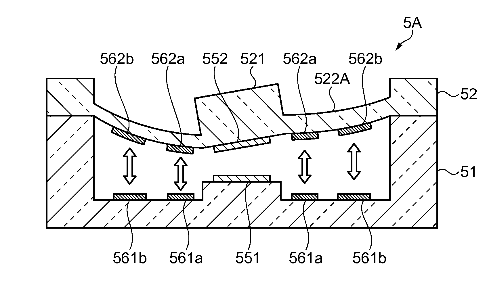
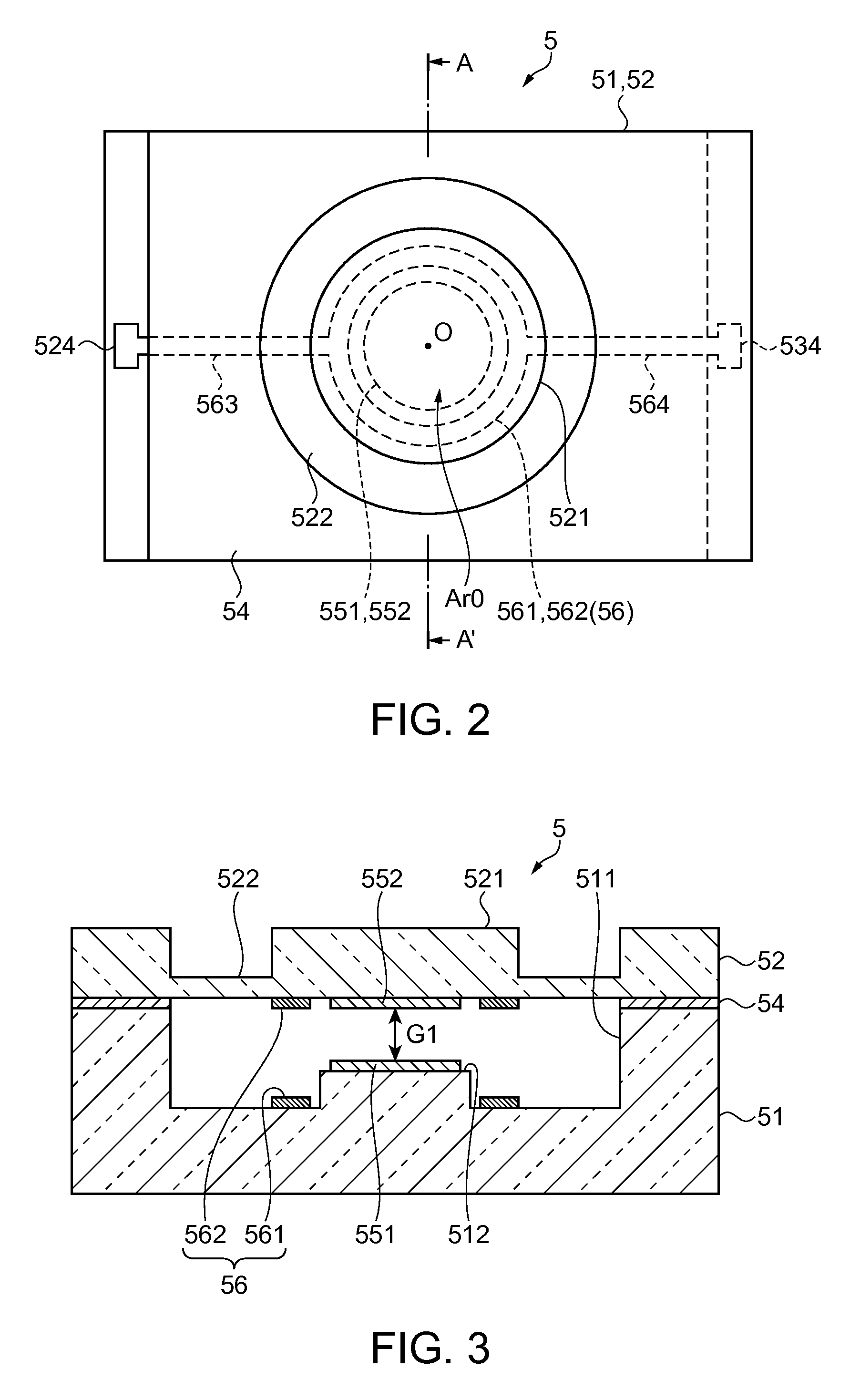
[0121]In the first embodiment, the electrostatic actuator 56 includes the ring-shaped first electrode 561 and second electrode 562 centering around the filter center point O. Therefore, since the electrostatic actuator 56 causes an electrostatic attraction to act on the movable portion 521 in a well-balanced manner with respect to the filter center point O, the gradient of the movable portion 521 (second reflection layer 552) may be small in some cases even when the inter-layer gap G1 is changed. Also, with the configuration in which the movable portion 521 is held by the holding portion 522, the holding portion 522 with a low rigidity has a large amount of flexure and the amount of flexure of the movable portion 521 is restrained to a small amount.

[0122]In such a case, the influence of the reflectance characteristics of the reflection layers 551, 552 on the optical characteristics of the variable-wavelength interfer...

third embodiment

[0129]Next, a variable-wavelength interference filter according to a third embodiment of the invention will be described.

[0130]In the second embodiment, the thickness dimension of the holding portion 522A is made asymmetrical about the filter center point O, thus causing the movable portion 521 to have a gradient when an electrostatic attraction is applied by the electrostatic actuator 56. Meanwhile, the third embodiment is different from the second embodiment in that the thickness dimension of the holding portion 522 is uniform and that the position where the electrodes constituting the electrostatic actuator 56 are arranged is different.

[0131]FIG. 10 is a cross-sectional view of a variable-wavelength interference filter according to the third embodiment, where the inter-layer gap is changed. In FIG. 10, in order to facilitate understanding of the explanation, the gradient angle of the movable portion 521 and the position where the electrostatic actuator 56 is installed are exagger...


PUM

PropertyMeasurementUnit
second wavelengthaaaaaaaaaa

Abstract

A variable-wavelength interference filter includes: a first substrate; a second substrate facing the first substrate; a first reflection layer provided on a surface facing the second substrate, of the first substrate; a second reflection layer which is provided on a surface facing the first substrate, of the second substrate, and faces the first reflection layer via an inter-layer gap; and an electrostatic actuator which flexes the second substrate in a direction toward the first substrate and thus changes the inter-layer gap. The first reflection layer and the second reflection layer have a reflectance characteristic showing a higher reflectance to light with a second wavelength that is shorter than a first wavelength, than a reflectance to light with the first wavelength.

Description

BACKGROUND[0001]1. Technical Field[0002]The present invention relates to a variable-wavelength interference filter, an optical filter device, an optical module, and an electronic apparatus.[0003]2. Related Art[0004]According to the related art, a variable-wavelength interference filter is known in which a pair of reflection layers facing each other is provided and the distance between the reflection layers is changed to extract light with a predetermined wavelength from measuring target light (see, for example, JP-A-7-243963).[0005]The variable-wavelength interference filter (optical cavity) described in JP-A-7-243963 includes a first substrate and a second substrate facing each other, high reflection layers arranged on the respective substrates and facing each other via an inter-layer gap, and electrodes arranged on the respective substrates and facing each other. In such a variable-wavelength interference filter, by applying a voltage between the electrodes and thus deforming the ...

Claims


Application Information

Patent Timeline
Patent Type & Authority Patents(United States)
IPC IPC(8): G02B26/00G01J1/44G01J3/26G01J3/28G01J3/02G01N21/65G01J3/12
CPCG02B26/001G01J1/44G01J3/027G01J3/26G01J3/2823G01J2003/1247G01N21/658
Inventor MATSUSHITA, TOMONORI
Owner SEIKO EPSON CORP
Why Eureka
Try Eureka